
User manual


Installing Your 1785-BEM Module
Chapter 4
4-21
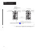
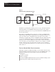
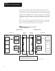
5. Connect one end of a 1770-CD cable to terminals 15, 16, and 17 on
the wiring arm of one of the 1785-BEM modules as shown in
Figure 4.15.
Figure 4.15
Channel
2B Connections Added Between a 1785-BEM Module
and Data Highway Plus Network or Remote I/O Link
1771 –P4S
Power Supply
1771 –P4S
Power Supply
1785 –BCM Module
Local I/O ChassisLocal I/O Chassis
1785 –BEM Module
1785 –BCM Module
1785 –BEM Module
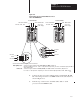
Data Highway Plus – connect the signal conductors with Clear, Shield, and Blue insulation to
terminals 15, 16, and 17 of 1785 –BEM modules respectively.
Remote I/O –connect the signal conductors with Blue, Shield, and Clear insulation to terminals 15, 16, and 17 of
1785 –BEM modules respectively.
Data Highway Plus
network or Remote I/O
19096
Channel 2B
See Note
Shield
See Note
Wire channel for either Data Highway Plus or Remote I/O.
PLC-5/40, -5/60, -5/80
PLC-5/40, -5/60, -5/80
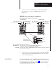
6. Connect the other end of the 1770-CD cable to terminals 1, 2, and 3
on the wiring arm of the Data Highway Plus network or remote I/O
link as shown in Figure 4.15.
Now that you’ve installed your 1785-BEM module, you are ready to start
up your system. Before doing so, double check all connections against the
procedures described in this chapter. Chapter 5 describes the operation of
the 1785-BCM module and the backup system and shows procedures for
starting up and operating your system.
What to Do Next