
User manual


Installing Your 1785-BEM Module
Chapter 4
4-11
T
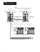
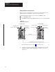
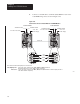
able 4.B
Configuring
Channels 2A and 2B
Configure Channel 2A switches
1
Configure Channel 2B switches
2
for:
1
4
2
5
3
6
Data Highway Plus network ON ON ON
Remote I/O – adapter mode using 57.6 kbaud ON ON OFF
Remote I/O – adapter mode using 115.2 kbaud ON OFF ON
Remote I/O – adapter mode using 230.4 kbaud ON OFF OFF
Relay switching or unused Channel
3
OFF ON ON
Remote I/O – scanner mode with 57.6 kbaud OFF ON OFF
Remote I/O – scanner mode with 115.2 kbaud OFF OFF ON
Remote I/O – scanner mode with 230.4 kbaud OFF OFF OFF
1
Switches 1, 2, and 3 determine configuration for Channel 2A.
2
Switches 4, 5, and 6 determine configuration for Channel 2B.
3
Does not function as a smart switch but as a relay with contacts either opened or closed. Also, set
the switches in this configuration if you are not going to use this channel.
Important: The positions of the switches are read at module power-up. If
the position of the switches is changed after module power-up, the
1785-BEM module will not recognize the new position.
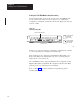
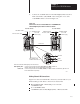
Inserting the 1785-BEM Module into the I/O Chassis
To insert the 1785-BEM module in your I/O chassis, perform the following
steps. We recommend that you insert you 1785-BEM module into the
right-most slot of the first I/O module group in the I/O chassis. The
1785-BEM module must be in the same module group (as defined by
2-slot addressing) with the 1785-BCM module.
ATTENTION: Remove power from the 1771 I/O chassis
backplane and wiring arm before removing or installing an I/O
module.
- Failure to remove power from the backplane or wiring arm could
cause module damage, degradation of performance, or injury.
- Failure to remove power from the backplane could cause injury or
equipment damage due to possible unexpected operation.