
User manual

Installing Your PLC-5 Backup System
Chapter 3
3-15
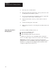
3. Perform steps 1 and 2 for the other PLC-5 programmable controller
and 1785-BCM module.
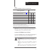
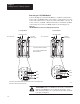
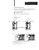
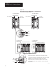
4. Connect a 1770-CD cable to terminals 15, 16, and 17 on each of the
1785-BCM wiring arms as shown in Figure 3.9.
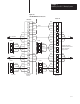
Figure 3.9
Remote
I/O Connections Added Between 1785-BCM Modules
17983
PLC-5 processor PLC-5 processor
HSSL was previously connected but is not shown for clarity.
Connections show default configuration with Channel 1A as Data Highway Plus and Channel 1B as Remote I/O scanner.
Local
I/
O Ch
ass
i
s
1785-BCM Moddule
1771-P4S
power supply
1771-P4S
power supply
Local
I/
O Ch
ass
i
s
1785-BCM Moddule
Blue
Shield
Clear
Blue
Shield
Clear
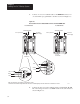
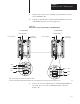
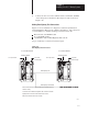
5. Connect one end of a 1770-CD cable to terminals 15, 16, and 17 on
the wiring arm of one of the 1785-BCM modules as shown in
Figure 3.10.