
User manual

Installing Your PLC-5 Backup System
Chapter 3
3-9
T
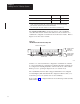
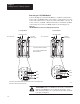
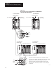
able 3.F
Configuring
1785-BCM Series B Channels 1A and 1B using SW2
Configure Channel 1A switches
1
Configure Channel 1B switches
2
for:
1
4
2
5
3
6
Data Highway Plus network at 57.6 kbaud (refer to Chapter 5, section
“Secondary Processor Remote Programming”)
ON ON ON
Remote I/O – adapter mode using 57.6 kbaud ON ON OFF
Remote I/O – adapter mode using 115.2 kbaud ON OFF ON
Remote I/O – adapter mode using 230.4 kbaud ON OFF OFF
Relay switching or unused Channel
3
OFF ON ON
Remote I/O – scanner mode with 57.6 kbaud OFF ON OFF
Remote I/O – scanner mode with 115.2 kbaud OFF OFF ON
Remote I/O – scanner mode with 230.4 kbaud OFF OFF OFF
1
Switches 1, 2, and 3 determine configuration for Channel 1A.
2
Switches 4, 5, and 6 determine configuration for Channel 1B.
3
Does not function as a smart switch but as a relay with contacts either opened or closed. Also, set
the switches in this configuration if you are not going to use this channel.
Important: The positions of the switches are read at the module power-up.
If the position of the switches is changed after module power-up, the
1785-BCM module does not recognize the new position.
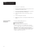
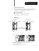
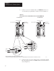
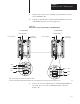
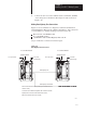
Inserting the 1785-BCM Module into the I/O Chassis
To insert the 1785-BCM module in your I/O chassis, perform the following
steps. We recommend that you insert your 1785-BCM module into the
left-most slot of the first I/O module group in the I/O chassis.
ATTENTION: Remove power from the 1771 I/O chassis
backplane and wiring arm before removing or installing an I/O
module.
Failure to remove power from the backplane or wiring arm
could cause module damage, degradation of performance, or
injury.
Failure
to remove power from the backplane
could cause injury
or equipment damage due to possible unexpected operation.