
User manual


Understanding the 1785-BCM
Hardware Components
Chapter 2
2-6
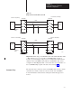
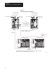
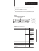
There are two switch assemblies located at the top and at the bottom of the
1785-BCM module. Refer to Figure 2.4 for locations of the switch
assemblies. Refer to Table 2.C for a description of the function of the
1785-BCM module switch assemblies.
Figure 2.4
1785-BCM
Module Switch Assemblies
Switch Assembly SW1
Switch Assembly SW2
Top View
Bottom View
19084
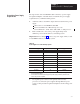
T
able 2.C
1785-BCM Module Switch Assembly Functions
Use this switch assembly: To:
SW1 • establish communication between the 1785-BCM
series B module and a 1785-BCM series A module.
• establish the fast data transfer mode from the
secondary module to the secondary processor.
SW2 • specify if Channels 1A and 1B are going to establish
communication with Data Highway Plus network or
with the remote I/O link. With the remote I/O link,
determine the baud rate as well as the mode of
operation of the processor (scanner or adapter).
To set the switches described above, refer to Chapter 5, “Operating Your
PLC-5 Backup System.”
Switch
Assemblies