
User manual


Sample Programs
Appendix A
A-13
T
able
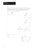
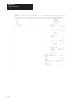
A.B
Data
T
able Typical T
ransfer Time Using Method 1 Program
with Minimal Program Scan (3–8 ms)
Number of Blocks
Being Transferred
Number of Words
Being Transferred
Transfer Time (in ms)
for Series A BCM
(see notes 1 & 2)
Transfer Time (in ms)
for Series B BCM
Fast Transfer Mode
Enabled (see notes 1,
3, & 4)
1 62 230 40–110
3 186 330–820 50–120
7 434 440–1500 50–160
10 620 1100–1700 60–210
16 992 1900–3300 140–280
1
These times can significantly change based on program scan. But an increase in the number of
blocks does not significantly affect program scan.
2
Times were taken using a PLC-5/25 processor.
3
Series B BCM module with fast mode disabled is roughly double the times shown.
4
Times were taken using a PLC-5/40 processor with one channel configured for DH+ and three
channels configured for remote I/O scanner at 230 kbaud.
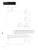
The method 2 differs from method 1 in that the primary system transfers
more than one block in the same program scan. These blocks make up a
segment that can be from 1 to 16 blocks (PLC-5/15 or PLC-5/25
processor) or from 1 to 64 block (PLC-5/20, -5/30, -5/40, -5/60, or -5/80
processor). You determine the number of blocks needed to transfer
information for your application.
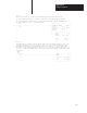
Data File Organization
Data file organization for the program sample for method 2 is the same as
described for method 1. Again, when you develop your program, use
whatever files you want.
Program File Organization
As in our program sample for method 1, file 2 contains the main program.
This program contains rungs that determine if the processor is primary or
secondary and the first BTR and BTW instructions.
Method 2 Sample –
Transferring Data Multiple
Blocks at a Time