
User manual


Chapter
8
8-1
Diagnosing Faults
This chapter describes how to diagnose faults with your PLC-5 backup
system using:
status indicators on the front of the module
bits in the system status word (word 1 of the BTR instruction)
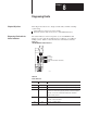
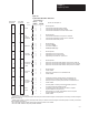
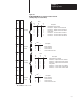
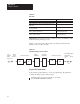
The status indicators on the front panel of your 1785-BCM module
(Figure 8.1) show both the normal and error conditions of your PLC-5
backup system. Table 8.A lists the indicators and what they indicate.
Figure 8.1
1785-BCM
Module Status Indicators
17978
Primary
Secondary
Backplane
Serial Communication Link (HSSL)
Fault
T
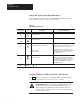
able 8.A
Status
Indicators
Indicator Color of LED This LED indicates:
PRI green when on — the 1785-BCM module belongs to the primary system
SEC green when on — the 1785-BCM module belongs to the secondary system
BPLN green when blinking — the 1785-BCM module is executing a block transfer
instruction or communicating properly with the I/O chassis backplane
when off — there is no communication between the 1785-BCM
module and the processor
SER green when blinking — proper HSSL communication
when off — failure in the HSSL
FLT red when on — hardware failure
Chapter Objectives
Diagnosing Faults with the
Status Indicators