Allen-Bradley PLC-5 Backup Communication Module (1785-BCM, 1785-BEM) product icon User Manual
Important User Information Because of the variety of uses for this product and because of the differences between solid state products and electromechanical products, those responsible for applying and using this product must satisfy themselves as to the acceptability of each application and use of this product. For more information, refer to publication SGI-1.1 (Safety Guidelines For The Application, Installation and Maintenance of Solid State Control).
Summary of Changes Summary of Changes Summary of Changes This release of the publication contains new updated information. To help you find updated information in this release of the manual, we have included change bars as shown to the left of this paragraph.
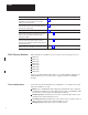
Preface Using This Manual Manual Objectives This manual shows you how to use 1785-BCM series B backup communication modules with a PLC-5 programmable controller (PLC-5/15 series B, -5/20, -5/25, -5/30, -5/40, and -5/60 processors). These modules enable high-speed communication transfer between two PLC-5 processors and provide system backup should the processor or other equipment in the system fail.
Preface If you want to read about: Refer to chapter: two methods you can use to program your backup system; considerations for using instructions that can cause problems in your backup system. 7 – Programming Techniques 1785-BCM module faults (as indicated by the module’s status indicators and bits of the system status word) and procedures for correcting faults. 8 – Diagnosing Faults specifications for the 1785-BCM module.
Preface Switchover is the transfer of I/O control from the primary processor to the secondary processor. Bumpless switchover is the transfer of I/O control from the primary processor to the secondary processor where the operation of the process being controlled is not affected. Asynchronous processing is processing where the ladder program scan and the block-transfer scan operate independently of each other within the same scan time.
Table of Contents Backup Concepts for the PLC-5 System Chapter 1 Chapter Objectives . . . . . . . . . . . . . . . . . . . . . . . . . . . . . . . . . . . Why Use a Backup System? . . . . . . . . . . . . . . . . . . . . . . . . . . . . Applying 1785-BCM Backup Communication Modules to the PLC-5 Programmable Controller . . . . . . . . . . . . . . . . . . . . . . What to do Next . . . . . . . . . . . . . . . . . . . . . . . . . . . . . . . . . . . . . .
Table of Contents Operating Your PLC-5 Backup System Chapter 5 Switchover Considerations Chapter 6 Chapter Objectives . . . . . . . . . . . . . . . . . . . . . . . . . . . . . . . . . . . How the 1785-BCM Module Operates . . . . . . . . . . . . . . . . . . . . How the Backup System Operates . . . . . . . . . . . . . . . . . . . . . . . Starting the Backup System . . . . . . . . . . . . . . . . . . . . . . . . . . . . . Powering Up the Backup System . . . . . . . . . . . . . . . . . . . . . . . .
Table of Contents Sample Programs Appendix A Appendix Objectives . . . . . . . . . . . . . . . . . . . . . . . . . . . . . . . . . . . . . . . A-1 Method 1 Sample – Transferring Data One Block at a Time . . . . . . . . A-1 Method 2 Sample – Transferring Data Multiple Blocks at a Time . . . . A-13 Reference Information Appendix B Appendix Objectives . . . . . . . . . . . . . . . . . . . . . . . . . . . . . . . . . . . . . . . Answers to PLC-5 Backup Configuration Questions . . . . . . . . . . . . . .
Chapter 1 Backup Concepts for the PLC-5 System Chapter Objectives This chapter describes concepts for using a backup system with your programmable controller. In addition, this chapter provides an overview of a PLC-5 processor backup system that uses 1785-BCM backup communication modules and a system that also uses 1785-BEM backup expansion modules.
Chapter 1 Backup Concepts for the PLC-5 System Applying 1785-BCM Backup Communication Modules to the PLC-5 Programmable Controller A PLC-5 system configured with 1785-BCM modules provides high speed backup communication and switchover of the Data Highway Plus and remote I/O links.
Chapter 1 Backup Concepts for the PLC-5 System Figure 1.1 PLC-5 Backup System Configuration Using 1785-BCM Module Only Local I/O Chassis Local I/O Chassis 1785 –BCM Module 1785 –BCM Module 1771 –P4S Power Supply PLC-5 processor PLC-5 processor 1771 –P4S Power Supply HSSL Data Highway Plus Remote I/O Do not put modules for controlling your process in local I/O chassis.
Chapter 1 Backup Concepts for the PLC-5 System Figure 1.2 PLC-5 Backup System Configuration Using 1785-BCM and 1785-BEM Modules Local I/O Chassis 1785 –BCM Module PLC –5/60 or –5/40 Local I/O Chassis 1785 –BEM Module 1785 –BEM Module 1785 –BCM Module 1771 –P4S Power Supply 1771 –P4S Power Supply PLC –5/60 or –5/40 Do not put modules for controlling your process in local I/O chassis.
Chapter 1 Backup Concepts for the PLC-5 System How the PLC-5 Backup System Works In the PLC-5 backup configuration, one system (consisting of one PLC-5 processor, 1785-BCM module, power supply, and chassis) controls the operation of the remote I/O. This system is referred to as the primary system. The other system is ready to take control of the remote I/O in the event of a fault in the primary system. This is referred to as the secondary system.
Chapter 1 Backup Concepts for the PLC-5 System Switchover Should a fault occur in the primary processor, control switches to the secondary system in less than 50 ms (maximum). When a switchover occurs, the outputs in the remote I/O maintain their last state until they come under the control of the secondary processor. However, keep in mind that the program scans of the two processors are not synchronized.
Chapter 1 Backup Concepts for the PLC-5 System transfer of control from the primary processor to the secondary when one of the following conditions is detected by the secondary processor: - communication timeout in the High Speed Serial Link (HSSL) between the two 1785-BCM modules and primary system is not updating the remote I/O - transfer of control command from the primary 1785-BCM module substitution of equipment without interruption of the process; that is, the faulted system can be repaired while the
Chapter 2 Understanding the 1785-BCM Hardware Components Chapter Objectives This chapter describes the major components that make up the 1785-BCM module. These components include: status indicators 1771-WG wiring arm 1785-BCM communication links - high-speed serial link (HSSL) - Data Highway Plus link (DH+) - remote I/O link (RIO) customer relay (contact) switch assemblies backplane interface Refer to Chapter 4 for information about the 1785-BEM backup expansion module.
Chapter 2 Understanding the 1785-BCM Hardware Components All indicators light at power up or when a hardware fault occurs in the 1785-BCM module. With the exception of the FLT indicator, all of the 1785-BCM module’s indicators are related to individual bits of the system status word. For more information on the system status word, refer to Chapter 5, “Operating Your PLC-5 Backup System.” For information about locating faults using the status indicators, refer to Chapter 8, “Diagnosing Faults”.
Chapter 2 Understanding the 1785-BCM Hardware Components Figure 2.
Chapter 2 Understanding the 1785-BCM Hardware Components Table 2.A Communication Ports Communication Port: This link is used to: High Speed Serial Link (HSSL) permit two-way alternating communication (half-duplex) between the two 1785-BCM modules of the backup system at a distance of up to 15 feet. Channel 1A connect the primary PLC-5 processor to the Data Highway Plus network or to the remote I/O link; the secondary processor is isolated from this link.
Chapter 2 Understanding the 1785-BCM Hardware Components Figure 2.
Chapter 2 Understanding the 1785-BCM Hardware Components Switch Assemblies There are two switch assemblies located at the top and at the bottom of the 1785-BCM module. Refer to Figure 2.4 for locations of the switch assemblies. Refer to Table 2.C for a description of the function of the 1785-BCM module switch assemblies. Figure 2.4 1785-BCM Module Switch Assemblies Switch Assembly SW1 Top View Switch Assembly SW2 Bottom View 19084 Table 2.
Chapter 2 Understanding the 1785-BCM Hardware Components I/O Backplane Interface Through its connection with the I/O chassis backplane, the 1785-BCM module can execute block transfer read (BTR) and block transfer write (BTW) instructions from a PLC-5 processor. With the inherent block-transfer queuing capabilities of the PLC-5 processor, multiple block-transfer instructions per program scan can be executed to the same 1785-BCM module.
Chapter 3 Installing Your PLC-5 Backup System Chapter Objectives This chapter provides an overview of an installed PLC-5 backup system and describes procedures for installing your PLC-5 backup system (1785-BCM series B module only).
Chapter 3 Installing Your PLC-5 Backup System Figure 3.1 PLC-5 Backup System Configuration Local I/O Chassis Local I/O Chassis 1785 –BCM Module 1785 –BCM Module 1771 –P4S Power Supply PLC-5 processor PLC-5 processor 1771 –P4S Power Supply HSSL Data Highway Plus Remote I/O Do not put modules for controlling your process in local I/O chassis.
Chapter 3 Installing Your PLC-5 Backup System Determining Power Supply Requirements The logic circuit of the 1785-BCM module is driven by a power supply through the backplane of the I/O chassis. Determine the power supply requirements for your PLC-5 backup system: 1. Add these values to determine output current needed from the power supply. 1.0A at 5V for a 1785-BCM module and 2.5A for the PLC-5/15 or PLC-5/25 processor or 3.3A for PLC-5/11, -5/20, -5/30, -5/40, -5/60, or -5/80 processor 2.
Chapter 3 Installing Your PLC-5 Backup System Setting the I/O Chassis Switches The I/O chassis switch assembly is located on the left side of the chassis backplane. Table 3.B lists the settings we recommend for the local chassis of your PLC-5 backup system. (Local refers to the chassis with the PLC-5 processor and the 1785-BCM module.) You can set remote system switches for your specific application.
Chapter 3 Installing Your PLC-5 Backup System Table 3.C Terminate PLC-5/15 or -5/25 Backup System DH+ and Remote I/O Links Set SW3 switch To this position: 1 ON – indicating that the PLC-5 processor is on the end of the remote I/O link 1 OFF – indicated that PLC-5 processor is not on the end of the remote I/O link 2 ON – indicating that PLC-5 processor is on the end of the DH+ link 2 OFF – indicating that PLC-5 processor is not on the end of the DH+ link Table 3.
Chapter 3 Installing Your PLC-5 Backup System Keying Your I/O Chassis Use the plastic keying bands, shipped with each I/O chassis, to key the chassis slot to accept only the 1785-BCM module. The module circuit board is slotted in two places on the rear edge. The position of the keying bands on the backplane connector must correspond to these slots to allow insertion of the module.
Chapter 3 Installing Your PLC-5 Backup System The 1785-BCM series B module switch assembly SW1 is preset at the factory to operate: with another 1785-BCM series B module in the Fast Data-Transfer mode. Fast data-transfer mode means that when the secondary module receives a data block, it immediately enables it to be read by the secondary processor. Figure 3.3 1785-BCM Series B Switch Assembly SW1 Switch Assembly SW1 Toggle pushed toward top OFF (open). Toggle pushed toward bottom ON (closed).
Chapter 3 Installing Your PLC-5 Backup System When: Set this switch: To this position: switch 3 is always unused 3 OFF (opened) switch 4 is always unused 4 OFF (opened) 1 To be compatible with 1785-BCM series A modules, you must set these switches as shown. If you use this module with a series A module and do not set switch assembly SW2 as shown, the LEDs on the series B module will flash. 2 This switch applies when both modules are 1785-BCM series B modules only.
Chapter 3 Installing Your PLC-5 Backup System Table 3.F Configuring 1785-BCM Series B Channels 1A and 1B using SW2 Configure Channel 1A switches1 1 2 3 switches2 4 5 6 Data Highway Plus network at 57.6 kbaud (refer to Chapter 5, section “Secondary Processor Remote Programming”) ON ON ON Remote I/O – adapter mode using 57.6 kbaud ON ON OFF Remote I/O – adapter mode using 115.2 kbaud ON OFF ON Remote I/O – adapter mode using 230.
Chapter 3 Installing Your PLC-5 Backup System Connecting Your PLC-5 Backup System 1. Turn off power to the I/O chassis. 2. Place the module in the plastic tracks on the top and bottom of the slot that guides the module into position. 3. Do not force the module into its backplane connector. Apply firm, even pressure on the module to seat it properly. 4. Snap the chassis latch over the top of the module to secure its position. 5. Connect the wiring arm to the module. 6.
Chapter 3 Installing Your PLC-5 Backup System Figure 3.
Chapter 3 Installing Your PLC-5 Backup System Connecting the 1785-BCM Modules Connect the High Speed Serial Link (HSSL) to establish communication between the 1785-BCM modules of the primary system and the secondary system. The cable for these connections can be a maximum of 15 feet. To do this, connect a 1770-CD or Belden 9463 cable to terminals 1, 2, and 3 on the wiring arm of each 1785-BCM module as shown in Figure 3.6. Figure 3.
Chapter 3 Installing Your PLC-5 Backup System Making Remote I/O Connections Figure 3.7 shows Channel 1B configured to establish communication with the remote I/O scanner mode (default configuration). The connections you must make for your PLC-5 backup system are between the: PLC-5 and the 1785-BCM module two 1785-BCM modules 1785-BCM module and Remote I/O Adapter module Steps to make these connections follow the figure. Figure 3.
Chapter 3 Installing Your PLC-5 Backup System 1. Connect one end of a 1770-CD cable to the REM I/O connector on one of the PLC-5 programmable controllers as shown in Figure 3.8. Figure 3.
Chapter 3 Installing Your PLC-5 Backup System 3. Perform steps 1 and 2 for the other PLC-5 programmable controller and 1785-BCM module. 4. Connect a 1770-CD cable to terminals 15, 16, and 17 on each of the 1785-BCM wiring arms as shown in Figure 3.9. Figure 3.
Chapter 3 Installing Your PLC-5 Backup System Figure 3.10 Remote I/O Connections Added Between 1785-BCM Module and Remote I/O Adapter Module Local I/O Chassis Local I/O Chassis 1785-BCM Module 1785-BCM Module PLC-5 processor PLC-5 processor 1771-P4S power supply 15 Blue 16 Shield 17 Clear 1771-ASB Remote Adapter Module Remote I/O Chassis No. 1 1771-P4S power supply 1771-ASB Remote Adapter Module Remote I/O Chassis No. n HSSL was previously connected but is not shown for clarity.
Chapter 3 Installing Your PLC-5 Backup System 6. Connect the other end of the 1770-CD cable to terminals 1, 2, and 3 on the wiring arm of the Rer mote I/O Adaptor module as shown in Figure 3.10. Making Data Highway Plus Connections Figure 3.11 shows Channel 1A configured to establish communication with Data Highway Plus network (default configuration).
Chapter 3 Installing Your PLC-5 Backup System 1. Connect one end of a 1770-CD cable to the PEER COMM INTFC connector on one of the PLC-5 programmable controllers, as shown in Figure 3.12. Figure 3.
Chapter 3 Installing Your PLC-5 Backup System 2. Connect the other end of the 1770-CD cable to terminals 12, 13, and 14 on the wiring arm of the 1785-BCM module in the same chassis as shown in Figure 3.12. 3. Perform steps 1 and 2 for the other PLC-5 programmable controller and 1785-BCM module. 4. Connect a 1770-CD cable to terminals 9, 10, and 11 on the wiring arm of each 1785-BCM module as shown in Figure 3.13. Figure 3.
Chapter 3 Installing Your PLC-5 Backup System 5. Connect the 1770-CD cable from the Data Highway Plus network to 9, 10, and 11 on the wiring arm of one of the 1785-BCM modules as shown in Figure 3.14. Figure 3.
Chapter 4 Installing Your 1785-BEM Module Chapter Objectives This chapter: describes the 1785-BEM backup expansion module identifies major components of the 1785-BEM module provides an overview of an installed PLC-5/40, -5/60, or -5/80 backup system provides procedures for determining power supply requirements provides procedures for installing your 1785-BEM modules provides procedures for connecting the 1785-BEM modules in the PLC-5 backup system Backup Expansion Module The 1785-BEM is the backup exp
Chapter 4 Installing Your 1785-BEM Module Status Indicators The 1785-BEM module has two status indicators on the front panel of the module (Figure 4.1). Figure 4.1 1785-BEM Module Status Indicators BACKUP E X P A N S IO N Run Fault 19087 RUN (green) indicator is on to show normal operation of the 1785-BEM module. FLT (red) indicator is on when a hardware fault is detected in the 1785-BEM module. Note that these indicators light at power up or when a hardware fault occurs in the 1785-BEM module.
Chapter 4 Installing Your 1785-BEM Module Wiring Arm You make connections to your communication links with the 1771-WG wiring arm, which is shipped with the module. Your wiring arm attaches to the pivot bar on the bottom of the I/O chassis. It pivots upward and connects with the module so that you can install or remove the module without disconnecting the wires.
Chapter 4 Installing Your 1785-BEM Module As shown in Figure 4.2, there are two user-configurable ports (Channels 2A and 2B) that support remote I/O or Data Highway Plus modes. Table 4.A lists the communication ports and describes how the system uses each port. Table 4.
Chapter 4 Installing Your 1785-BEM Module Figure 4.3 Relays for Processor A and Processor B Processor B (secondary) Processor A (primary) 1785-BCM 1785-BEM 1785-BEM 1785-BCM PLC-5 PLC-5 2A 2A 2B 2B 1A 1A 1B 1B DH+/RIO DH+/RIO Processor B (primary) Processor A (secondary) 1785-BCM 1785-BEM PLC-5 1785-BEM 1785-BCM PLC-5 2A 2A 2B 1A 2B 1B 1B 1A DH+/RIO DH+/RIO 11679I Customer Relay The customer relay connection on the 1785-BEM module is used to switch external devices.
Chapter 4 Installing Your 1785-BEM Module Switch Assembly The 1785-BEM module has a switch assembly which specifies if Channels 2A and 2B are going to establish communication with Data Highway Plus network or with the remote I/O link. When the module establishes communication with the remote I/O link, the switch also determines the baud rate and the mode of operation of the processor (scanner or adapter). To set these switches, refer to the section on “Setting the Switch Assembly.
Chapter 4 Installing Your 1785-BEM Module Installing the 1785-BEM Module The installation procedures for the 1785-BEM backup expansion module are: determining power supply requirements setting the 1785-BEM module switches keying the I/O chassis inserting the module into the chassis ATTENTION: In the backup system, switch 1 of the local I/O chassis should be in OFF position in order to allow the switchover when a fault is detected.
Chapter 4 Installing Your 1785-BEM Module Figure 4.4 PLC-5 Backup System Configuration (using a 1785-BEM module) Local I/O Chassis 1785-BCM module Local I/O Chassis 1785-BEM module PLC-5/40 or -5/60 1785-BCM module 1771-P4S Power Supply PLC-5/40 or -5/60 HSSL BCM DH+ or RIO BEM DH+ or RIO 1785-BEM module 1771-P4S Power Supply Do not put modules for controlling your process in local I/O chassis. BEM RIO BCM DH+ or RIO DH+ or RIO (BEM module) Remote I/O (BEM module) Remote I/O Chassis No.
Chapter 4 Installing Your 1785-BEM Module Electrostatic Discharge Damage ATTENTION: Under some conditions, electrostatic discharge can degrade performance or damage the module. Observe the following precautions to guard against electrostatic damage. Wear an approved grounded wrist strap or touch a grounded object to discharge potential before handling the module. Do not touch the backplane connector or connector pins.
Chapter 4 Installing Your 1785-BEM Module Setting the 1785-BEM Module Switch Assembly Switch assembly SW2, located at the bottom of the 1785-BEM module, has six switches. The function of the six switches is to establish the configuration of Channels 2A and 2B of the module. Figure 4.6 shows the location of SW2. Figure 4.6 Switch Assembly SW2 Switch Assembly SW2 Toggle pushed toward top OFF (open). Bottom View Toggle pushed toward bottom ON (closed).
Chapter 4 Installing Your 1785-BEM Module Table 4.B Configuring Channels 2A and 2B Configure Channel 2A switches1 1 2 3 Configure Channel 2B switches2 4 5 6 Data Highway Plus network ON ON ON Remote I/O – adapter mode using 57.6 kbaud ON ON OFF Remote I/O – adapter mode using 115.2 kbaud ON OFF ON Remote I/O – adapter mode using 230.4 kbaud ON OFF OFF Relay switching or unused Channel3 OFF ON ON Remote I/O – scanner mode with 57.
Chapter 4 Installing Your 1785-BEM Module Connecting Your 1785-BEM Module 4-12 1. Turn off power to the I/O chassis. 2. Place the module in the plastic tracks on the top and bottom of the slot that guides the module into position. 3. Do not force the module into its backplane connector. Apply firm, even pressure on the module to seat it properly. 4. Snap the chassis latch over the top of the module to secure it in position. 5. Connect the wiring arm to the module. 6.
Chapter 4 Installing Your 1785-BEM Module Figure 4.
Chapter 4 Installing Your 1785-BEM Module Making Channel 2A Connections Figure 4.8 shows the Channel 2A connections you must make for your PLC-5 backup system. These connections are between the: PLC-5/40 or PLC-5/60 processor and the 1785-BEM module two 1785-BEM modules 1785-BEM module and Data Highway Plus network or remote I/O link Figure 4.
Chapter 4 Installing Your 1785-BEM Module Figure 4.9 Channel 2A Connections Added Between a PLC-5 Processor and 1785-BEM Module Local I/O Chassis 1785-BCM module Local I/O Chassis 1785-BEM module PLC-5/40, -5/60, -5/80 1771-P4S power supply 1785-BCM module 1785-BEM module PLC-5/40 or -5/60 1771-P4S power supply See Note Shield See Note See Note Shield See Note Wire channel for either Data Highway Plus or Remote I/O.
Chapter 4 Installing Your 1785-BEM Module 4. Connect a 1770-CD cable to terminals 9, 10, and 11 on each of the 1785-BEM wiring arms as shown in Figure 4.10. Figure 4.
Chapter 4 Installing Your 1785-BEM Module 5. Connect the 1770-CD cable from the Data Highway Plus network or Remote I/O link to 9, 10, and 11 on the wiring arm of one of the 1785-BEM modules as shown in Figure 4.11. Figure 4.
Chapter 4 Installing Your 1785-BEM Module Figure 4.12 Channel 2B Connections Local I/O Chassis Local I/O Chassis 1785 –BEM Module 1771 –P4S Power Supply 1785 –BCM Module PLC-5/40, -5/60, -5/80 1785 –BCM Module PLC-5/40, -5/60, -5/80 1785 –BEM Module 1771 –P4S Power Supply Channel 2B Data Highway Plus network or Remote I/O link 1785-BCM module was connected in Chapter 3 but is not shown for clarity. Also, 1785-BEM module Channel 2A was previously connected but is not shown for clarity. 19093 1.
Chapter 4 Installing Your 1785-BEM Module Figure 4.13 Channel 2B Connections Added Between a PLC-5 and a 1785-BEM Module Local I/O Chassis Local I/O Chassis 1785 –BEM Module 1771 –P4S Power Supply 1785 –BCM Module PLC-5/40, -5/60, -5/80 See Note 1785 –BCM Module PLC-5/40, -5/60, -5/80 18 See Note 19 Shield 20 See Note 1785 –BEM Module 1771 –P4S Power Supply Shield See Note Wire channel for either Data Highway Plus or Remote I/O.
Chapter 4 Installing Your 1785-BEM Module 4. Connect a 1770-CD cable to terminals 15, 16, and 17 on each of the 1785-BEM wiring arms as shown in Figure 4.14. Figure 4.
Chapter 4 Installing Your 1785-BEM Module 5. Connect one end of a 1770-CD cable to terminals 15, 16, and 17 on the wiring arm of one of the 1785-BEM modules as shown in Figure 4.15. Figure 4.
Chapter 5 Operating Your PLC-5 Backup System Chapter Objectives In this chapter we describe how the primary system transfers data to the secondary system.
Chapter 5 Operating Your PLC-5 Backup System Figure 5.1 Automatic Transfer of Data Over Remote I/O HSSL Primary Secondary PLC-5 PLC-5 1785-BCM 1785-BCM Remote I/O 11053I In addition to providing the secondary processor a copy of the remote discrete input image table, the 1785-BCM modules in both systems work together to provide the secondary processor a copy of block transfer read (BTR) data from the remote I/O chassis.
Chapter 5 Operating Your PLC-5 Backup System Sequence of Transfer The sequence of transfer from the primary to the secondary system is as follows: 1. The data from the primary processor’s data table is sent to the primary 1785-BCM module by means of a Block Transfer Write (BTW) instruction. 2. The data is sent to the secondary 1785-BCM module over the HSSL. 3. The secondary processor reads the data from the secondary 1785-BCM module by means of a Block Transfer Read (BTR) instruction.
Chapter 5 Operating Your PLC-5 Backup System This scheme, where status and block identification information are always present, permits continuous verification of the data transfer, and if necessary, the re-sending of a block of data if that block was not successfully transmitted. In addition, the 1785-BCM modules exchange the status word over the HSSL continuously (even when the processors are not in RUN mode). This constant communication allows the modules to always have information about each other.
Chapter 5 Operating Your PLC-5 Backup System Important: When programming block transfer instructions, you must specify the LENGTH field (Figure 5.3) as 0, since the 1785-BCM module determines that size in accordance with its status (primary or secondary) and type of instruction (BTW or BTR). Figure 5.
Chapter 5 Operating Your PLC-5 Backup System Figure 5.4 BTR Instruction Words 15 14 13 12 11 10 09 08 07 06 REMOTE STATUS 05 04 03 03 01 00 LOCAL STATUS BLOCK IDENTIFICATION 62 WORDS OF DATA (IN SECONDARY PROCESSOR ONLY) Important: The lower byte of the status word is for the LOCAL status. These bits indicate status of the 1785-BCM module installed in the same chassis as the processor to which you are referring. The upper byte of the status word refers to REMOTE status.
Chapter 5 Operating Your PLC-5 Backup System Status Bit Description 8 Serial communication error; when on, this bit indicates a communication error in the high speed serial link (HSSL) 9 I/O chassis backplane error; when on, this bit indicates a communication error in the transfer of data from the PLC-5 processor to its 1785-BCM module. See bit 1.
Chapter 5 Operating Your PLC-5 Backup System When the primary 1785-BCM module receives the last block (block ID = number of blocks in segment) through a BTW instruction, the module returns a block number equal to 1 in the next BTR instruction. This re-initializes the data transmission process.
Chapter 5 Operating Your PLC-5 Backup System Figure 5.5 BTW Instruction Words 15 14 13 12 11 10 09 08 07 06 05 04 03 03 01 00 Bits NUMBER OF BLOCKS IN SEGMENT Word 1 BLOCK IDENTIFICATION1 Word 2 62 WORDS OF DATA (PRIMARY PROCESSOR ONLY) Word 3 . . . Word 64 11057I 1 Reserved for future use Word 1: Number of Blocks in Segment — In the BTW instruction, word 1 has different meanings depending on whether the system is primary or secondary.
Chapter 5 Operating Your PLC-5 Backup System With 1785-BCM module, 32 input bits are available in the PLC-5 processor image table. (The 32 output bits in the output image table are unused and reserved.) These input words are called Auxiliary Diagnostics/Status Words and they provide further information about the 1785-BCM module and the 1785-BEM backup expansion module in both the primary and secondary systems. Refer to Figure 5.6. Figure 5.
Chapter 5 Operating Your PLC-5 Backup System Table 5.C Extended Status Bits (W1) Bit1 Description 10 1785-BCM series A module; when on, this bit indicates that the other 1785-BCM module is series A. 11 Fast Data Transfer mode; when on, this bit indicates that the data valid bit is set to 1 (one) as soon as the secondary module receives a data block. When off, this bit indicates that the data valid bit is 1 (one) only when the secondary module receives the complete data segment.
Chapter 5 Operating Your PLC-5 Backup System Each byte of word W2 is divided into two groups of four bits corresponding to the module’s channels (Figure 5.7). The three least-significant bits of each group corresponds to three switches of switch assembly SW2 which is used to specify the configuration of module channels. The most-significant bit corresponds to the error bit for the respective channel.
Chapter 5 Operating Your PLC-5 Backup System This means that if you set both processors node addresses to n, the programming device can communicate with the secondary processor with the node address n+1. For example, a primary processor with node number 16 on Data Highway Plus network has the same address switch setting as the secondary processor node.
Chapter 5 Operating Your PLC-5 Backup System To provide status information, or to pass additional block transfer values, you must provide support ladder programming. Refer to Chapter 7, “Programming Techniques” and Appendix A “Sample Programs” for information on developing ladder programs for the backup system.
Chapter 5 Operating Your PLC-5 Backup System Figure 5.9 Execution of Primary Program Primary 1785-BCM module Primary Processor BTR 2 words 1. At program initialization, 1785-BCM module specifies block ID of 1 so that BTW are initiated in correct sequence. Block ID = 1 BTW 64 words 3. When primary 1785-BCM module receives data block without errors, it sends data to secondary 1785-BCM module over the HSSL. 2. Primary processor sends data to primary 1785-BCM module.
Chapter 5 Operating Your PLC-5 Backup System The primary 1785-BCM module sends several data blocks that make up a segment sent to the secondary 1785-BCM module. Until the secondary 1785-BCM module correctly receives all blocks of the segment, the data valid bit returned to its local processor through the BTR instruction will not turn on. This bit will turn on only when the complete segment is correctly received and the number of blocks in the segment match that sent by the primary 1785-BCM module.
Chapter 5 Operating Your PLC-5 Backup System For example, if the primary processor is sending multiple blocks to the secondary processor, the data that was in block 2 when block 1 was sent may change by the time block 2 is sent. This is because the ladder program, which executes asynchronously to block transfer instructions, may have changed the information in block 2 before it was sent.
Chapter 5 Operating Your PLC-5 Backup System Starting the Backup System After you have checked your program for proper data to be transferred, and have developed the transmitting and receiving programs, you can start the backup system. To start the backup system: 5-18 1. Apply power to the primary system. 2. Apply power to the secondary system. 3. Load the application program and the remote I/O configuration in the primary PLC-5 processor by addressing node n. 4. Test the system. 5.
Chapter 5 Operating Your PLC-5 Backup System Powering Up the Backup System If a power loss occurs in both the primary and secondary systems once the backup system has been started up, use the following power-up sequence: ATTENTION: When you connect a 1785-BCM series B module to a 1785-BCM series A module, ensure you have properly set switch 1 of switch assembly SW1. Otherwise, if you power up both systems, both modules will assume to be the primary. 1. Switch both PLC-5 processors to PROGRAM mode. 2.
Chapter 5 Operating Your PLC-5 Backup System Restarting a Repaired Backup System Once a faulted system has been repaired, you may restart it as described below. You do not need to power-down or change the mode of the operating system to restart the system. 1. Switch the repaired processor to PROGRAM mode and apply power. This way, the processor automatically becomes the secondary (backup). 2.
Chapter 5 Operating Your PLC-5 Backup System Editing or Programming On-line To avoid a control switch from the primary to the secondary processor when you attempt to edit the ladder program or data table of the primary PLC-5 processor using a programming device: 1. Do not switch the primary PLC-5 processor to REMOTE PROGRAM mode. Switch the primary PLC-5 processor to REMOTE RUN mode.
Chapter 6 Switchover Considerations Chapter Objectives When planning programs for the PLC-5 backup system, you must first consider that the program scans of the two processors are not synchronized; that is, the program in the primary processor is not executing the exact same instruction at the same time as the program in the secondary processor.
Chapter 6 Switchover Considerations Input Signal Update Time Immediately after the switchover, it is possible that the secondary processor will be reading different input conditions. To avoid a sudden change in the outputs during switchover, all of the input signals must be present for at least a time equal to the sum of: program scan I/O scan input module delay 1785-BCM switchover time If these conditions are not met, outputs may be assigned different states in the two processors.
Chapter 6 Switchover Considerations Using the 1785-BCM module, the primary system can transfer data to the secondary system at a maximum throughput of 4K words in less than 1 second. This time takes into account: program scan programming method used to transfer data to secondary processor PLC-5 block-transfer queuing number of remote I/O chassis number of remote I/O block transfers For actual data table transfer times when transferring different block lengths of data, refer to Appendix A “Sample Programs.
Chapter 6 Switchover Considerations Forcing I/O Backup communication functions provided by the PLC-5 backup system do not transfer the force tables from the primary to the secondary processors. Thus, if the PLC-5 backup system has forces set in the primary processor, the forces do not transfer to the secondary processor. For this situation, if a switchover occurs, the secondary processor becomes active, but the forces set in the original primary processor are not carried over.
Chapter 6 Switchover Considerations The other stations on the link initiate a token recovery procedure which includes: recreating the active node table rebuilding the link, including the new primary processor ensuring that one node gains control of the link During this time, while the stations reconstruct the link, communication is interrupted. The length of this time depends on the number of stations involved in the link, and the number of messages received and/or transmitted.
Chapter 6 Switchover Considerations Table 6.A DH+ Switchover Scenarios If the new primary is: the following could occur causing this result Polling the link Message packet from another station disrupted The source station turns on error bit in its MSG instruction (You provide programming at the source station to regain synchronization with the receiving station. You can do this by monitoring the message instruction error bit as a condition for re-transmitting the message.
Chapter 6 Switchover Considerations The secondary processor (remote I/O scanner or adapter) is not part of the remote I/O link, but is communicating with the secondary 1785-BCM’s smart switch interface. When the secondary processor is configured for scanner mode, this interface responds to a poll from the secondary processor’s scanner with actual data it receives from the primary processor over the HSSL. The scanner “thinks” that it is communicating with the real remote I/O adapters.
Chapter 6 Switchover Considerations Figure 6.1 Block Diagram of Remote I/O Switch 1785-BCM HSSL link (to primary 1785-BCM Copy of remote I/O data including block transfers Smart-switch interface Remote I/O link Secondary processor I/O scanner/adapter Carrier-detect circuit 11106I To determine the maximum time it takes for the secondary module to close its relays after it detects a switchover, consider the following: the primary scanner has just requested a 64-word BTR from the remote module at 57.
Chapter 6 Switchover Considerations Data Table Considerations Several of the data table sections in the PLC-5 processor are not structured with single 16-bit words. You need to consider this when applying the 1785-BCM module. For example, the BTW of the primary processor transfers 62 words of data to the secondary processor (plus the packet length and block ID word). Some structures such as timers, counters, and floating point control files have three words.
Chapter 6 Switchover Considerations Because the secondary processor’s program scan and block transfer execution are totally asynchronous, it is possible for the secondary processor to operate on partial data structures. If the secondary processor is executing instructions that operate on any of the multi-word structures that are listed above, the following sequence of events may occur: 1. The 1785-BCM transfers the first word of a multi-word structure to the secondary processor.
Chapter 6 Switchover Considerations Should the 1785-BCM module transfer one or more of these values to the secondary system and the primary system fails, the data table of the secondary system will contain intermediate values for an indeterminate amount of time, thus creating illegal BCD values.
Chapter 6 Switchover Considerations What to Do Next 6-12 In this chapter, you read about switchover considerations for the PLC-5 backup system. By accounting for these considerations in your program, you can execute a smoother and faster switchover should the primary processor fault. Read the next chapter to learn about two different programming techniques you can use when you program your PLC-5 backup system. Read also to learn about program instructions that can cause problems during switchover.
Chapter 7 Programming Techniques Chapter Objectives Read this chapter to familiarize yourself with techniques used to program your PLC-5 backup system. In this chapter we describe: how to get started with a program to transfer data table values two methods you can use to program the PLC-5 backup system to transfer data table values the behavior of specific instructions when used in your application program, and give you suggestions for dealing with these instructions.
Chapter 7 Programming Techniques Figure 7.
Chapter 7 Programming Techniques Programming Methods to Transfer Data Table Values This manual provides two solutions to programming your PLC-5 backup system to transfer data table values. These methods are: transferring data one block at a time transferring data multiple blocks at a time We describe the operation of these programming methods on the following pages. To view sample programs that use these methods, refer to appendix A, “Sample Programs.
Chapter 7 Programming Techniques Program Operation in the Primary System In the primary system’s program, COP instructions move data with a block ID of 1 to the BTW data file of the primary processor, where it remains until a block ID of 2 (1+1) is requested through a BTR of the primary 1785-BCM module. When this happens, another COP instruction is enabled. This COP moves data with a block ID of 2 to the BTW data file, where it remains until a block ID of 3 (2+1) is requested by the 1785-BCM module.
Chapter 7 Programming Techniques In addition, the secondary 1785-BCM module compares the segment length specified in the secondary program’s BTW instruction with the segment length sent by the primary 1785-BCM module. If the segment lengths are different, the secondary 1785-BCM module turns on the programming error bit (bit 3 is local, bit 11 is remote). Figure 7.2 shows how a program that uses the one-block-at-a-time method works. Figure 7.
Chapter 7 Programming Techniques Method 2 — Transferring Data Multiple Blocks at a Time In the second method, transferring data multiple blocks at a time, the application program takes advantage of the PLC-5 block transfer queue. Because the PLC-5 processor assigns the task of block transfer to one microprocessor and program scan to another, block transfers are executed asynchronously and simultaneously in relation to the scanning of the program, permitting multiple block transfers per scan.
Chapter 7 Programming Techniques Program Operation in the Primary System The primary processor’s program executes the 3 BTW instructions to the primary 1785-BCM module. After the 3 blocks have been transferred, the BTR shows that the next block to be sent is 1. In this way, once the 1785-BCM module confirms that the number of the last block sent (3) equals the size of the segment, the module requests a transfer of new data.
Chapter 7 Programming Techniques Figure 7.
Chapter 7 Programming Techniques Accounting for Instructions That Could Cause Problems During Switchover Some instructions, when used with a PLC-5 backup system, may operate unpredictably when a switchover occurs if you fail to observe certain programming considerations. For example, you must consider transferring the control element and data elements for instructions that are also being executed in the secondary processor. You also must consider transferring data files which contain more than one word.
Chapter 7 Programming Techniques The hardware timer of the primary processor is completely asynchronous to the hardware timer of the secondary processor. If the whole three word timer structure, including this timer byte is transferred from the primary to the secondary processor during a switchover, then the timer could encounter a large positive increment in the timer accumulated value. The worst-case increment may be up to 2.55 seconds, which may cause a large bump.
Chapter 7 Programming Techniques As with the timer instruction, your program should transfer the counter accumulated value from the primary to the secondary processor at least once after you: start up the backup system switch the secondary PLC-5 from PROGRAM to RUN mode restart a repaired system This allows the accumulated value in the secondary processor to track the accumulated value in the primary processor.
Chapter 7 Programming Techniques Block Transfer Instructions It is impossible to guarantee that both processors are executing a given BTW or BTR at the same time, since the remote I/O scans are not synchronized, and since the block transfer data is not transferred instantaneously by both PLC-5 processors. The BTR files in the secondary processor always reflect information contained in the primary processor, except with a time delay.
Chapter 7 Programming Techniques Summary of Programming Considerations When developing a program for the PLC-5 backup system, you must always consider the following: non-synchronous I/O scans execution times of block transfer instructions time for transfer of data from the primary to the secondary processor the need to reduce the quantity of data to be transferred, and gathering all related data into a single block synchronization of discrete I/O data with regard to program scans even though remote I/O sc
Chapter 8 Diagnosing Faults Chapter Objectives This chapter describes how to diagnose faults with your PLC-5 backup system using: status indicators on the front of the module bits in the system status word (word 1 of the BTR instruction) Diagnosing Faults with the Status Indicators The status indicators on the front panel of your 1785-BCM module (Figure 8.1) show both the normal and error conditions of your PLC-5 backup system. Table 8.A lists the indicators and what they indicate. Figure 8.
Chapter 8 Diagnosing Faults Primary (PRI) and Secondary (SEC) LED Indicators Table 8.B lists the possible states of the PRI and SEC LEDs and provides the recommended actions to take in case of a fault. Table 8.
Chapter 8 Diagnosing Faults Table 8.C BPLN, SER, and FLT LED Indicators If this LED is: BPLN Description Recommended Action normal operation no action required SER FLT BPLN PLC-5 processor is in PROGRAM mode (normal operation) SER FLT BPLN block-transfer instruction fault; no block-transfer has been requested Check that the PLC-5 is in RUN mode. Check the program. Also check to see that the module is properly inserted in the I/O chassis.
Chapter 8 Diagnosing Faults Diagnosing Faults with Bits of the System Status Word In the 1785-BCM module, two bits of the status word serve to inform the PLC-5 processor of the state of the local and remote system. (The local system refers to that system whose 1785-BCM module is in the same chassis as the PLC-5 processor that is being monitored.) Figure 8.2 shows both local and remote bits and describes what is occurring in the system when the bits turn off or on.
Chapter 8 Diagnosing Faults Figure 8.2 System Status Word Error Indications Remote BCM module bits 8 9 10 11 12 13 14 15 Local BCM module bits Error If bit condition is: 1 Remote Local BCM bit BCM bit then the error description is: 0 HSSL 0 0 1 1 1 I/O chassis backplane 0 0 1 1 0 1 0 1 Normal operation. Communication fault between local processor and BCM Communication fault between remote processor and BCM Communication fault in both systems.
Chapter 8 Diagnosing Faults Diagnosing Faults with Bits of the Auxiliary Diagnostic/Status Words Bits of the two Auxiliary Diagnostics/Status Words provide further information about the 1785-BCM backup module and 1785-BEM backup expansion module (if any). Important: The auxiliary diagnostic/status word bits in Figure 8.3 and Figure 8.4 are in an octal representation (bits numbered 0–7 and 10–17).
Chapter 8 Diagnosing Faults Figure 8.4 BCM and BEM Modules Configuration Status Word W2 (Auxiliary Diagnostic/Status Word) 10 0 11 1 12 2 Bits 1 11 1 12 2 Channel B Config 1 1 1 1 0 0 0 0 1 1 0 0 1 1 0 0 10 0 Description 1 0 1 0 1 0 1 0 Data Highway Plus network Remote I/O – adapter mode at 57.6 kbaud Remote I/O – adapter mode at 115.2 kbaud Remote I/O – adapter mode at 230.4 kbaud Relay switch Remote I/O – scanner mode at 57.6 kbaud Remote I/O – scanner mode at 115.
Chapter 9 Specifications Specifications The following specifications are for a 1785-BCM series B module and a 1785-BEM series A module. Compatible Processors Module Location PLC-5/15 series B, -5/20, -5/25, -5/30, -5/40, and -5/60 processors 1771 I/O Chassis (local) Backplane Current BCM 1.0A @ 5V dc BEM 0.
Appendix A Sample Programs Appendix Objectives This appendix provides two sample programs to help you understand the following programming methods described in Chapter 7: method 1 – Transferring Data One Block at a Time method 2 – Transferring Data Multiple Blocks at a Time You can use either of the sample programs described in this chapter (with slight modification to account for your application) to program your backup system.
Appendix A Sample Programs Table A.A Data Files This information: Is in file: BTR and BTW control files and storage words N30 BTR data files (this is where the 1785-BCM module sends BTR data) N31 BTW data files (this is where the 1785-BCM module obtains BTW data) N32 Buffered data from the primary processor that you want to timers, counters, devices, etc. N33 (secondary program only) Data you want to send to the secondary processor, e.g.
Appendix A Sample Programs Program file 9 contains the secondary subroutine. This file: checks the block ID of the BTR moves the BTR data to the proper address in file N33 Program file 10 contains the primary subroutine: This file: stores the block ID of the BTR sets the BTW block ID equal to the BTR block ID moves the data from N34 to the BTW file Program file 11 provides diagnostic rungs that count errors in the program.
Appendix A Sample Programs SAMPLE 1771–BCM 1ATATIME PROGRAM Program Listing Report PLC–5/25 28 August 1991 Page 1 File 1ATATIME Rung 2:0 Rung 2:0 THIS RUNG WILL OBTAIN STATUS INFORMATION FROM THE BCM AND WHEN THE PROCESSOR IS SECONDARY IT WILL ALSO OBTAIN DATA FROM THE BCM.
Appendix A Sample Programs Rung 2:2 | |1=LOCAL IS | | PROG TO |PRIMARY PRIMARY | | RUN DELAY |STORE BIT SUB | | T29:0 N31:0 +JSR––––––––––––––––––––+ | +––––] [––––––––] [––––––––––––––––––––––––––––––––––+JUMP TO SUBROUTINE +–+ | DN 0 |Prog file number 10| | | |Input par | | | |Return par | | | +–––––––––––––––––––––––+ | Rung 2:3 | |1=REMOTE | | PROG TO |IS PRIMARY SECONDARY | | RUN DELAY |STORE BIT SUB | | T29:0 N31:0 +JSR–––––––––––––––+ | +––––] [––––––––] [–––––––––––––––––––––––––––––––––––––––+JUMP
Appendix A Sample Programs Rung 2:5 THIS SUBROUTINE MONITORS THE BLOCK TRANSFER WRITES, READS, READ STATUS DATA AND INCREMENTS COUNTERS ON ERRORS. PARTS OF THIS SUBROUTINE MAY BE DELETED BASED ON USER PREFERENCE OR THE ENTIRE SUBROUTINE MAY BE DELETED IF MEMORY IS CRITICAL.
Appendix A Sample Programs Rung 9:0 THIS IS THE SECONDARY SUBROUTINE. THIS RUNG EXAMINES THE DATA FROM THE BCM, CHECKS THE BID, AND MOVES IT TO THE PROPER DESTINATION IN FILE N33. THE DATA IN N33 CAME FROM THE PRIMARY PROCESSOR FILE N34.
Appendix A Sample Programs Rung 10:0 OPTIONAL RUNG THAT CAN BE USED TO JUDGE DATA TRANSFER TIME BY COMPARING N34:10 IN THE PRIMARY TO N33:10 IN THE SECONDARY. | T4:0 +TON–––––––––––––––+ | +––]/[–––––––––––––––––––––––––––––––––––––––––––––++TIMER ON DELAY +–(EN)+–+ | DN ||Timer T4:0| | | | ||Time base 0.01+–(DN)| | | ||Preset 32767| | | | ||Accum 0| | | | |+––––––––––––––––––+ | | | | +MOV–––––––––––––––+| | | +–––––+MOVE ++ | | |Source T4:0.
Appendix A Sample Programs Rung 10:3 THIS IS THE PRIMARY SUBROUTINE. THIS RUNG EXAMINES THE BID REQUESTED AND THEN MOVES A BLOCK OF DATA FROM N34 TO THE BTW FILE. THE DATA IN FILE N34 OF THE PRIMARY WILL SHOW UP IN FILE N33 OF THE SECONDARY.
Appendix A Sample Programs Rung 11:0 | BTR | | BTR 1 ERROR | | ER COUNT | | N30:0 +CTU–––––––––––––––+ | +––––] [–––––––––––––––––––––––––––––––––––––––––––––+COUNT UP +–(CU)–+ | 12 |Counter C28:0| | | |Preset 999+–(DN) | | |Accum 0| | | +––––––––––––––––––+ | Rung 11:1 | BTW | | BTW 1 ERROR | | ER COUNT | | N30:5 +CTU–––––––––––––––+ | +––––] [–––––––––––––––––––––––––––––––––––––––––––––+COUNT UP +–(CU)–+ | 12 |Counter C28:1| | | |Preset 999+–(DN) | | |Accum 0| | | +––––––––––––––––––+ | Rung 11:2 DIAGNO
Appendix A Sample Programs Rung 11:3 N31:0/4 IS A USER DIAGNOSTIC FLAG INDICATING A LOCAL ERROR. THE BUFFER FULL BIT MAY NEED TO BE DELETED. | |LOCAL LOCAL | | |SERIAL ERROR | | BTR 1 |COMM.
Appendix A Sample Programs Rung 11:5 | USER | | DEFINED BTR | | ERROR ERROR | | RESET BIT COUNT | | I:010 C28:0 | +––––] [––––––––––––––––––––––––––––––––––––––––––––––––––––––––––+––(RES)–––+–+ | 00 | | | | |BTW | | | |ERROR | | | |COUNT | | | | C28:1 | | | +––(RES)–––+ | | | | | | |LOCAL | | | |SERIAL | | | |COMM.
Appendix A Sample Programs Table A.
Appendix A Sample Programs Program file 9 contains the secondary subroutine. This file: checks the block ID of the BTR and copies the BTR data with a series of rung pairs, for example, rungs 9:1 and 9:2. (Because we want to transfer 3 blocks at a time in this sample, the program contains 3 of these rung pairs. You can modify your program to transfer from 1 to 16 blocks per segment by adding or deleting rung pairs to this file.
Appendix A Sample Programs Rung 2:1 THIS RUNG DETERMINES PRI/SEC FUNCTIONALITY AND EXECUTES THE CORRESPONDING SUBROUTINE.
Appendix A Sample Programs Rung 2:4 THE BTW WILL SEND THE PACKET LENGTH, BLOCK ID AND, WHEN PRIMARY, IT WILL ALSO SEND DATA. WORD N30:182 IS A USER ADJUSTABLE VALUE THAT DETERMINES THE NUMBER OF BLOCKS SENT. THIS VALUE SHOULD BE CHANGED AND THE DATA FILES N33 AND N34 ADJUSTED TO MATCH THE PACKET SIZE.
Appendix A Sample Programs Rung 2:5 THIS SUBROUTINE MONITORS THE BLOCK TRANSFER WRITES, READS AND READ STATUS DATA AND INCREMENTS COUNTERS ON ERRORS. PARTS OF THIS SUBROUNTINE MAY BE DELETED BASED ON PACKET LENGTH OR THE ENTIRE SUBROUTINE MAY BE DELETED IF THE MEMORY IS CRITICAL.
Appendix A Sample Programs Rung 9:0 THIS IS THE START OF A SUBROUTINE PROGRAM FILE THAT WILL BE EXECUTED IN THE SECONDARY PROCESSOR TO BTR AND MOVE DATA RECEIVED FROM THE PRIMARY PROCESSOR. THIS PROGRAM FILE CONTAINS A PAIR OF RUNGS FOR EACH BLOCK READ (1–64) THAT PERFORM THE BTR AND MOVE THE DATA TO N33. (THIS RUNG IS A PAIR WITH RUNG 2:0). THE NUMBER OF RUNG PAIRS SHOULD EQUAL THE NUMBER OF BLOCKS YOU WANT TO SEND.
Appendix A Sample Programs Rung 9:2 THIS RUNG IS A PAIR WITH RUNG 9:1.
Appendix A Sample Programs Rung 9:4 THIS RUNG IS A PAIR WITH RUNG 9:3 .
Appendix A Sample Programs Rung 10:0 THIS IS THE START OF A SUBROUTINE PROGRAM FILE THAT WILL BE EXECUTED IN THE PRIMARY PROCESSOR TO MOVE AND BTW DATA TO THE SECONDARY PROCESSOR. THIS OPTIONAL RUNG CAN BE USED TO JUDGE DATA TRANSFER TIME BY COMPARING N34:10 IN THE PRIMARY TO N33:10 IN THE SECONDARY. | T4:0 +TON–––––––––––––––+ | +––]/[–––––––––––––––––––––––––––––––––––––––––––––++TIMER ON DELAY +–(EN)+–+ | DN ||Timer T4:0| | | | ||Time base 0.
Appendix A Sample Programs Rung 10:2 THERE IS A RUNG FOR EACH BLOCK WRITE (1–16) THAT PREFORMS THE BTW AND MOVES THE DATA FROM N34 TO THE PROPER BTW DATA FILE. TO ADJUST THIS PROGRAM DELETE EACH UNUSED BLOCK ID RUNG AND ADJUST WORD N30:182 TO THE DESIRED PACKET LENGTH.
Appendix A Sample Programs Rung 10:3 THIS RUNG IS SIMILAR TO RUNG 10:2.
Appendix A Sample Programs Rung 11:0 THIS IS THE START OF AN OPTIONAL SUBROUTINE PROGRAM FILE THAT IS USED FOR DIAGNOSTICS AND ERROR REPORTING. THIS RUNG MONITORS AND COUNTS BTR 1 ERRORS. | BTR 1 | | BTR 1 ERROR | | ER COUNT | | N30:0 +CTU–––––––––––––––+ | +––––] [–––––––––––––––––––––––––––––––––––––––––––––+COUNT UP +–(CU)–+ | 12 |Counter C28:0| | | |Preset 999+–(DN) | | |Accum 0| | | +––––––––––––––––––+ | Rung 11:1 THIS RUNG MONITORS AND COUNTS BTW 1 ERRORS.
Appendix A Sample Programs Rung 11:3 N31:0/4 IS A USER DIAGNOSTIC FLAG INDICATING A LOCAL ERROR. THE BUFFER FULL BIT MAY NEED TO BE DELETED. | |LOCAL LOCAL | | |SERIAL ERROR | | BTR 1 |COMM.
Appendix A Sample Programs Rung 11:5 THIS RUNG IS USED TO RESET THE ERROR COUNTERS. | USER | | DEFINED BTR 1 | | ERROR ERROR | | RESET BIT COUNT | | I:010 C28:0 | +––––] [––––––––––––––––––––––––––––––––––––––––––––––––––––––––––+––(RES)–––+–+ | 00 | | | | |BTR 2 | | | |ERROR | | | |COUNT | | | | C28:6 | | | +––(RES)–––+ | | | | | | |BTR 3 | | | |ERROR | | | |COUNT | | | | C28:7 | | | +––(RES)–––+ | | |LOCAL | | | |SERIAL | | | |COMM.
Appendix A Sample Programs Rung 11:6 THIS RUNG IS USED TO RESET THE ERROR COUNTERS. | USER | | DEFINED BTW 1 | | ERROR ERROR | | RESET BIT COUNT | | I:010 C28:1 | +––––] [––––––––––––––––––––––––––––––––––––––––––––––––––––––––––+––(RES)–––+–+ | 00 | | | | |BTW 2 | | | |ERROR | | | |COUNT | | | | C28:21 | | | +––(RES)–––+ | | | | | | |BTW 3 | | | |ERROR | | | |COUNT | | | | C28:22 | | | +––(RES)–––+ | You can add error count reset rungs here as required.
Appendix A Sample Programs Rung 11:9 THIS RUNG MONITORS AND COUNTS THE BTR 3 ERRORS. | BTR 3 | | BTR 3 ERROR | | ER COUNT | | N30:20 +CTU–––––––––––––––+ | +–+–––] [––––––––––––––––+–––––––––––––––––––––––––––+COUNT UP +–(CU)–+ | | 12 | |Counter C28:7| | | | |LOCAL | |Preset 999+–(DN) | | | |SERIAL | |Accum 0| | | |BTR 3 |COMM.
Appendix A Sample Programs Table A.
Appendix B Reference Information Appendix Objectives This appendix provides the following reference information:. answers to PLC-5 backup configuration questions formulas for determining delay and transfer times between the primary and secondary processors Answers to PLC-5 Backup Configuration Questions The following questions may arise when you are configuring a PLC-5 backup system.
Appendix B Reference Information Q. In which slot of the local I/O chassis do I install the 1785-BEM module? A. We recommend that you install the 1785-BEM module in the right-most slot of the first I/O module group in the I/O chassis for ease in making connections and programming. Note that the 1785-BEM module must be in the same I/O group as the 1785-BCM module. (Refer to Chapter 3 and Chapter 4 for more information.) Q. Does the 1785-BEM module have to go next to the 1785-BCM module? A. Yes.
Appendix B Reference Information Q. How do I configure the remote I/O chassis in the PLC-5 backup system? A. Any valid remote I/O chassis configuration is acceptable. For more information configuring remote I/O chassis, refer to the PLC-5 Enhanced and Ethernet Programmable Controllers User Manual (publication 1785-6.5.12). PLC-5 Family Programmable Controllers Installation Manual (publication 1785-6.6.1). Q. What power supply should I use to supply power to the PLC-5 backup system? A.
Appendix B Reference Information B-4 Q. Can I use a 1785-BCM Series B module with a 1785-BCM Series A module? A. Yes, when you properly set switch 1 of the switch assembly SW1 and switches of switch assembly SW2 of the 1785-BCM Series B module. (Refer to Chapter 3 for more information.) Q. Can the 1785-BEM backup expansion module work with the 1785-BCM Series A module? A. No. The 1785-BEM module can only work with the 1785-BCM Series B module. Q.
Appendix B Reference Information Determining Data Table Transfer Time Use Table B.A and Table B.B to estimate your data table transfer times. These tables provide tested values that are derived from method 1 and method 2 sample applications programs provided in Appendix A. Table B.
Appendix B Reference Information Table B.
Appendix C Using a Series A 1785-BCM Module Appendix Objectives This appendix briefly describes the differences between a 1785-BCM series A backup module and a 1785-BCM Series B backup module. 1785-BCM Series A Backup Module Characteristics The series A version of the 1785-BCM module has the following differences from the series B version of the 1785-BCM module. It communicates only with the PLC-5/15 and PLC-5/25 processor.
Appendix C Reference Information Figure C.1 1785-BCM Series A Module Communication Links 1 Sh 2 High Speed Serial Link 1 2 Customer Relay Not Used Not Used 1 Sh 2 1 Sh 2 1 Sh 2 1 Sh 2 To Network 1 Data Highway Plus From Controller To Remote I/O 2 Remote I/O at 57.
Index Numbers 1785-BCM module communication links, 2-2 compatibility, 1-7 customer relay, 2-5 features and capabilities, 1-6 hardware, 2-1 installation procedures, 3-5 relays, 2-4 series A module differences, C-1 smart switch interface, 6-7 status indicators, 2-1 switch assemblies, 2-6 system status word, 5-6 wiring arm, 2-2 1785-BEM module, 4-1 backup expansion, 1-7 communication links, 4-3 communication ports, 4-4 connecting channels, 4-12 customer relay, 4-5 I/O backplane interface, 4-6 installation pro
Index data table data transfer method of, 5-3 sequence of, 5-3 data transfer data in the data table, 5-2 overview, 1-5 remote input data, 5-1 default communication mode, 2-4 diagnosing faults with bits of auxiliary diagnostic/status word, 8-6 with bits of the system status word, 8-4 with status indicators, 8-1 diagnostic instructions, 7-11 disconnecting failed PLC-5 backup system, 5-18 discrete I/O delay, B-1 divergence, 6-3 E editing on-line, 5-20 electrostatic discharge information, 3-5, 4-9 F fast data
Index problem instructions block transfer, 7-12 counter, 7-10 diagnostic, 7-11 FIFO, 7-11 file arithmetic and logic, 7-11 message, 7-12 relay logic, 7-9 sequencing, 7-11 timer, 7-9 procedures 1785-BEM module installation, 4-7 connecting 1785-BEM channels, 4-12 connecting the 1785-BCM modules, 3-10 determining power supply requirements using 1785-BCM module, 3-3 determining power supply requirements using 1785-BEM module, 4-6 disconnecting/repairing a faulted system, 5-18 editing or programming online, 5-20
Index S sample programs transferring data multiple blocks at a time, A-13 transferring data one block at a time, A-1 secondary processor remote programming, 5-12 secondary program, 5-15 sequencing instructions, 7-11 Series A 1785-BCM compatibility, C-1 setting 1785-BCM module switch assemblies, 3-6 smart switch interface, 6-7 specifications, 9-1 starting up the PLC-5 backup system, 5-17 status indicators BPLN, SER, FLT, 8-2 description of, 2-1, 8-1 diagnosing faults, 8-1 diagnosing faults with, 8-2 PRI and
1995 Allen-Bradley Company, Inc. PLC is a registered trademark of Allen-Bradley Company, Inc. PLC-5 is a trademark of Allen-Bradley Company, Inc. Data Highway Plus is a trademark of Allen-Bradley Company, Inc.
Allen-Bradley has been helping its customers improve productivity and quality for 90 years. A-B designs, manufactures and supports a broad range of control and automation products worldwide. They include logic processors, power and motion control devices, man-machine interfaces and sensors. Allen-Bradley is a subsidiary of Rockwell International, one of the world’s leading technology companies. With major offices worldwide.