
User manual

Transferring Discrete and BlockTransfer Data
Chapter 8
8-3
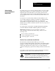
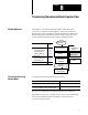
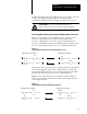
Figure 8.1
Automatic
I/O Transfer between Supervisory and
AdapterMode Processors
15298
0003040710131417 0003040710131417
0003040710131417 0003040710131417
Word
0
1
2
3
4
5
6
7
Word
0
1
2
3
4
5
6
7
Supervisory Processor
AdapterMode Processor
I:30 - I:37 (or adapter image file)
Supervisory Processor
AdapterMode Processor
O:30 - O:37 (or adapter image file)
Supervisory Processor
PLC2 0X0-0X7
PLC3 OXX0-OXX7
PLC5 O:X0-O:X7
Supervisory Processor
PLC2 1X0-1X7
PLC3 IXX0-IXX7
PLC5 I:X0-I:X7
Output File
Input File
Input File
Output File
Word 0 is reserved for block transfer and status.
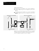
If data from the supervisory processor is intended to control outputs of the
adapter-mode processor, the ladder logic in the adapter-mode processor
must move the data from its input file (I/O rack 3 or the adapter image file)
to its output file (local I/O). Use XIC and OTE instructions for bit data;
use move and copy instructions for word data.
If you want the supervisory processor to read data from a data file in the
adapter-mode processor, ladder logic in the adapter-mode processor must
move that data to its output file (I/O rack 3 or the adapter image file) for
transfer to the supervisory processor.