
User manual
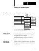

Planning Your System Programs
Chapter 6
6-6
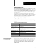
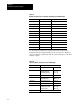
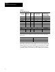
Table 6.C
Hardware
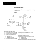
Requirements for the Inputs and Output of the Drill Example
Input Part Description
AUTO selector switch select automatic mode
LS1 N.O. limit switch part in place
LS2 N.C. limit switch drill station home
LS3 N.O. limit switch drill motor on
LS4 N.O. limit switch drill station at full depth
LS5 N.O. limit switch cycle complete
DSF drive motor move drill station forward
DSB drive motor move drill station back
DM drill motor drill motor on
CL1 electric clamp clamp 1 on
CMF drive motor move conveyor forward
TMR1 timer dwell timer
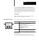
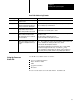
Use the hardware requirements (with the functional specification) to
match the inputs and outputs with the actions of the process. Table 6.D
shows the hardware requirements with the general description of the drill
machine example.
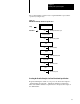
Table 6.D
List
of Conditions and Actions for the Drill Example
When this happens: This happens:
AUTO switch closes Conveyor moves forward (CMF = on)
LS1 closes Conveyor stops
Clamp holds wood
Drill station advances
(CMF = off)
(CL1 = on)
(DSF = on)
LS3 closes Drill motor starts (DM = on)
LS4 closes Drill station stops
Dwell timer starts
(DSF = off)
(TMR1 = on)
Timer done Drill station backs up (DSB = on)
LS3 opens Drill motor stop (DM = off)
LS2 opens Drill station stops
Clamp releases wood
Conveyor starts
(DSB = off)
(CL1 = off)
(CMF = on)
LS5 closes Wood is ejected