
User manual

Choosing Communication
Chapter 5
5-2
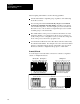
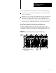
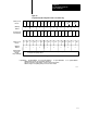
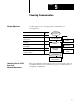
Figure 5.1
Processor
Front Panels
P
R
O
G
PLC5/10 Processor PLC5/12, 5/15,
and 5/25 Processors
Communication
Indicator
ACTIVE/FAULT
(green/red)
Keyswitch
Connect
programming
terminal here
Connect
DH+
link here
REM I/O Indicator
ACTIVE/FAULT
(green/red)
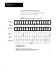
Adapter
Indicator
(green)
Connect
remote
I/O link here
Battery
Indicator (red)
Processor
RUN/FAULT
Indicator
(green/red)
FORCE
Indicator
(amber)
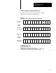
Write the DH+
network station
number on this label
PLC5 family
member
designation
Battery
Holder
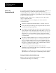
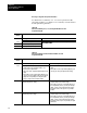
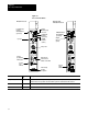
Connector Name Connector
Type
Description
Programming terminal 9pin, Dshell Use this connector to directly connect a programming terminal to the processor. This programming
terminal connector has a parallel connection with the 3pin DH+ communications link connector.
DH+ communications link 3pin Use this connector to connect to DH+ communications link.
Remote I/O 3pin Use this connector for the remote I/O link. (This connector is not available for a PLC5/10 processor.)