
User manual

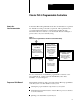
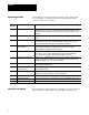

Table of Contents iii
Calculating
Program T
iming 91. . . . . . . . . . . . . . . . . . . . . . . .
Chapter
Objectives
91. . . . . . . . . . . . . . . . . . . . . . . . . . . . . . . . . . .
Introduction to Classic PLC5 Processor Scanning 91
. . . . . . . . . . . .
I/O ScanningDiscrete and Block Transfer 95
. . . . . . . . . . . . . . . . .
Instruction Timing and Memory Requirements 97
. . . . . . . . . . . . . . .
Program Constants 913
. . . . . . . . . . . . . . . . . . . . . . . . . . . . . . . . . .
Direct and Indirect Elements 913
. . . . . . . . . . . . . . . . . . . . . . . . . . . .
Maximizing System Performance 101. . . . . . . . . . . . . . . . . . . .
Chapter
Objectives
101. . . . . . . . . . . . . . . . . . . . . . . . . . . . . . . . . . .
Components of Throughput 101
. . . . . . . . . . . . . . . . . . . . . . . . . . . . .
Input and Output Modules Delay 101
. . . . . . . . . . . . . . . . . . . . . . . . .
I/O Backplane Transfer 102
. . . . . . . . . . . . . . . . . . . . . . . . . . . . . . . .
Remote
I/O Scan T
ime 102. . . . . . . . . . . . . . . . . . . . . . . . . . . . . . . .
Processor Time 106
. . . . . . . . . . . . . . . . . . . . . . . . . . . . . . . . . . . . .
Calculating Throughput 106
. . . . . . . . . . . . . . . . . . . . . . . . . . . . . . . .
Selecting Switch Settings A1. . . . . . . . . . . . . . . . . . . . . . . . .
Chassis Backplane with Classic PLC5 Processor A1. . . . . . . . . . . . .
Chassis Backplane with Adapter Module A2
. . . . . . . . . . . . . . . . . . .
Chassis Configuration Plug for Power Supply A3
. . . . . . . . . . . . . . . .
Remote I/O Adapter Module 1771ASB Series C without
Complementary I/O
A4. . . . . . . . . . . . . . . . . . . . . . . . . . . . . . . .
Remote I/O Adapter Module 1771ASB Series C with
Complementary I/O
A6. . . . . . . . . . . . . . . . . . . . . . . . . . . . . . . .
SW1 A7
. . . . . . . . . . . . . . . . . . . . . . . . . . . . . . . . . . . . . . . . . . . . .
AdapterMode ProcessorsSW2 in a PLC5 or Scanner Module A8
. .
AdapterMode ProcessorsSW2 in a PLC2/20, 2/30,
or Sub I/O Scanner Module System A9
. . . . . . . . . . . . . . . . . . . .
AdapterMode ProcessorsSW2 in a PLC3 or PLC5/250
System with 8Word Groups A10
. . . . . . . . . . . . . . . . . . . . . . . . .
AdapterMode ProcessorsSW2 in a PLC3 or PLC5/250
System with 4Word Groups A11
. . . . . . . . . . . . . . . . . . . . . . . . .
SW3 A12
. . . . . . . . . . . . . . . . . . . . . . . . . . . . . . . . . . . . . . . . . . . . .
Design Worksheets B1. . . . . . . . . . . . . . . . . . . . . . . . . . . . . .
Conventions Used in These Worksheets B1. . . . . . . . . . . . . . . . . . .
Prepare
a Functional Specification
B2. . . . . . . . . . . . . . . . . . . . . . . .
Determine Control Strategy B4
. . . . . . . . . . . . . . . . . . . . . . . . . . . . .
Identify Chassis Locations B6
. . . . . . . . . . . . . . . . . . . . . . . . . . . . .
Select Module T
ypes and List I/O Points
B7. . . . . . . . . . . . . . . . . . . .
Total
I/O Module Requirements
B9. . . . . . . . . . . . . . . . . . . . . . . . . .
Assign I/O Modules to Chassis and Assign Addresses B10
. . . . . . . . . .
Select Adapter Modules B12
. . . . . . . . . . . . . . . . . . . . . . . . . . . . . . .
Place System Hardware B14
. . . . . . . . . . . . . . . . . . . . . . . . . . . . . . .