
User manual

Assigning Addressing Modes,
Racks, and Groups
Chapter 4
4-15
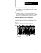
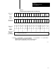
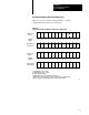
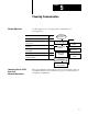
Placing the Modules with 1/2Slot Addressing
Figure 4.7 shows a possible module placement to configure
complementary I/O using 1/2-slot addressing.
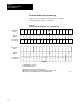
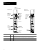
Figure 4.7
Complementary
I/O Configurations with 1/2Slot Addressing
IIO IOO
O
Double-slot
BT
E
M
P
T
Y
12
BT
OI
E
M
P
T
Y
OO I I O OI
I, O,
BT
IO
I
O
I
O
I
O
I
O
I
O
I
O
I
O
I
O
I
O
I
O
I
O
I
O
14261
1
01
01 23
23
45
45
67
67
01
01
23
23
45
45
67
67
01
01
23
23
45
45
67
67
33
Primary 12Slot
Chassis
I/O Group
Number
Complementary
12Slot Chassis
Complementary
12Slot Chassis
I/O Group
Number
Primary 12Slot
Chassis
Example A
Example B
I = Input Module (8, 16, 32point)
O = Output Module (8, 16, 32point)
BT = Block Transfer Module
1 Output modules use the same output image table bits
2 Can be input or output module (8 or 16point) singleslot block transfer module
3 Must be empty if corresponding primary slot is block transfer module