
User manual

Assigning Addressing Modes,
Racks, and Groups
Chapter 4
4-13
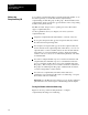
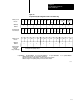
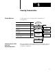
Figure 4.5
Complementary
I/O Configurations with 2Slot Addressing
I
O
I
O
O
I
BT
BT
BT
Double–slot
BT
Double–slot
BT
E
M
P
T
Y
E
M
P
T
Y
E
M
P
T
Y
E
M
P
T
Y
E
M
P
T
Y
E
M
P
T
Y
E
M
P
T
Y
021 34567
O
02134567
2
13
13079
3
3
333
8
I
8
8
O
8
16
16
O
8
O
8
8
8
O
16
O
8
O
8
I
8
I
8
O
8
O
8
O
8
O
8
O
8
I
16
16
I
16
O
16
I
16
I
16
I
16
I
16
I
16
I
16
O
16
O
16
O
16
O
16
O
16
O
16
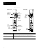
1
Primary 16Slot
Chassis
I/O Group
Number
Complementary
16Slot Chassis
Primary 16Slot
Chassis
I/O Group
Number
Complementary
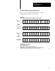
Chassis Not
Allowed
Except for Output
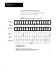
Outputs in the complementary chassis use the same bits in the output image table as
the outputs in the primary chassis.
I = Input Module O = Output Module BT = Block Transfer Module 8 = 8point I/O Modules 16 = 16 point I/O Modules
1 Output modules use the same output image transfer bits
2 Can be 8point input or output module or singleslot block transfer module
3 Must be empty if corresponding primary slot is block transfer module
Example A
Example B