
User manual

Assigning Addressing Modes,
Racks, and Groups
Chapter 4
4-9
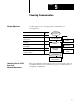
Summary
Table 4.A summarizes the guidelines for selecting an addressing mode.
Table 4.A
Addressing
Mode Summary
Addressing
Mode
Guidelines
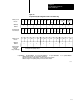
2slot
• Two I/O module slots = 1 group
• Each physical 2slot I/O group corresponds to one word (16 bits) in the input image table and one word
(16 bits) in the output image table
• When you use 16point I/O modules, you must install as a pair an input module and an output module in
an I/O group; if you use an input module in slot 0, you must use an output module in slot 1 (or it must be
empty). This configuration gives you the maximum usage of I/O.
• You cannot use a blocktransfer module and a 16point module in the same I/O group because
blocktransfer modules use 8 bits in both the input and output table. Therefore, 8 bits of the 16point
module would conflict with the blocktransfer module.
• You cannot use 32point I/O modules.
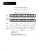
1slot
• One I/O module slot = 1 group
• Each physical slot in the chassis corresponds to one word (16 bits) in the input image table and one
word (16 bits) in the output image table
• When you use 32point I/O modules, you must install as a pair an input module and an output module in
an even/odd pair of adjacent I/O group; if you use an input module in slot 0, you must use an output
module in slot 1 (or it must be empty). This configuration gives you the maximum usage of I/O.
• Use any mix of 8 and 16point I/O modules, blocktransfer or intelligent modules in a single I/O chassis.
Using 8point modules results in fewer total I/O.
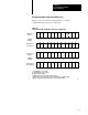
1/2slot
• One half of an I/O module slot = 1 group
• Each physical slot in the chassis corresponds to two words (32 bits) in the input image table and two
words (32 bits) in the output image table
• Use any mix of 8, 16, and 32point I/O or blocktransfer and intelligent modules. Using 8point and
16point I/O modules results in fewer total I/O.
• With the processorresident local rack set for 1/2slot addressing, you cannot force the input bits for the
upper word of any slot that is empty or that has an 8point or 16point I/O module. For example, if you
have an 8point or a 16point I/O module in the first slot of your local rack (words 0 and 1 of the I/O
image table, 1/2slot addressing), you cannot force the input bits for word 1 (I:001) on or off.
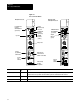
The number of racks in a chassis depends on the chassis size and the
addressing mode:
If using this
chassis size:
With 2slot
addressing,
rack type is:
With 1slot
addressing,
rack type is:
With 1/2slot
addressing,
rack type is:
4slot 1/4 rack 1/2 rack 1 rack
8slot 1/2 rack 1 rack 2 racks
12slot 3/4 rack 11/2 racks 3 racks
16slot 1 rack 2 racks 4 racks
Assigning
Racks