
User manual

Assigning Addressing Modes,
Racks, and Groups
Chapter 4
4-8
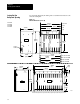
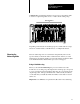
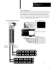
Using 1/2Slot Addressing
When you select 1/2-slot addressing, the processor addresses one-half of
an I/O module slot as one I/O group. Each physical slot in the chassis
corresponds to two input and two output image-table words. The type
(unidirectional or bidirectional) and density of the module that you install
determines the number of bits that are used in each word.
IIOO
2
3
0
1
Not
Used
Always
0
0
1
2
3
4
5
6
7
0
1
2
3
4
5
6
7
4
5
6
7
Word #
Word #
Output Image Table
I
nput
I
mage
T
a
bl
e
14974
I/O Group Designation
Input/Output Designation
I/O Chassis with 1/2Slot Addressing
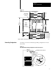
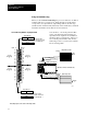
You can mix 8-, 16- and 32-pt I/O modules
in any order in the I/O chassis because 32
input bits and 32 output bits are available in
the image table for each I/O slot. When you
use 8- and 16-pt I/O modules with 1/2-slot
addressing, however, you use fewer total I/O
bits in our image table.
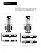
Input Word 0
Output Word 0
ImageTable
Words Allocated
for I/O Group 0
Input Word 1
Output Word 1
ImageTable
Words Allocated
for I/O Group 1
#
00
02
04
06
-
10
12
14
16
-
00
02
04
06
-
10
12
14
16
-
#
01
03
05
07
-
11
13
15
17
-
01
03
05
07
-
11
13
15
17
-
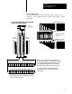
Unused
17 010 7
17 10 07
17 10 07
17 10 07
Unused
1/2-Slot
I/O Group
0
1/2-Slot
I/O Group
0
1/2-Slot
I/O Group
1
1/2Slot
I/O Group
1
Input
Input
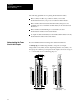
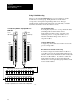
1/2Slot
I/O Group with One 32pt Input Module
This I/O group uses two words of the image table.