
User manual

Chapter
4
4-1
Assigning Addressing Modes,
Racks, and Groups
This chapter conveys basic hardware addressing concepts and gives you
guidelines with which to choose the addressing modes (including
complementary I/O), racks, and groups to use in your system.
If you want to read about: Go to
page:
Placing I/O modules in chassis 41
Understanding terms 42
Choosing I/O addressing mode 43
Rack number assignments 49
Addressing complementary I/O 412
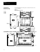
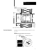
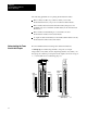
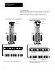
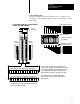
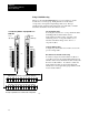
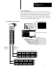
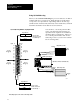
Place I/O modules in a chassis depending on the electrical characteristics
of the modules. The placement is made left to right, with the left-most
position being closest in the chassis to the PLC-5 processor or the I/O
adapter module. The placement order is as follows:
1. block-transfer modules (all types)
2. dc input modules, placed left to right from lowest to highest voltages
3. dc output modules, placed left to right from lowest to highest voltages
4. ac input modules, placed left to right from lowest to highest voltages
5. ac output modules, placed left to right from lowest to highest voltages
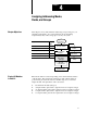
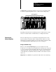
Chapter
Objectives
Placing I/O Modules
in Chassis
System Design
Determined
Choosing
Communication
Transferring Discrete
and Block Data
Planning Your
System Programs
Calculating Program
Timing
Assigning Addressing
Mode, Racks,
and Groups
Choosing Hardware
Placing System
Hardware
Selecting Interrupt
Routines