
User manual

Placing System Hardware
Chapter 3
3-6
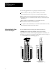
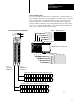
Use 6.35 mm (0.25 inch) mounting bolts to attach the I/O chassis to the
enclosure backpanel.
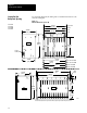
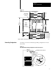
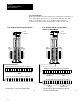
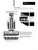
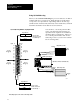
Figure 3.1
Chassis
Dimensions (Series B)
315mm
(12.41")
Power
Connector
254mm
(10")
Side
193mm
1
(7.60")
591mm
(23.25")
464mm
(18.25")
337mm
(13.25")
210mm
(8.25")
171mm
(6.75")
610mm
(24.01")
483mm
(19.01")
356mm
(14.01")
229mm
(9.01")
16slot 1771A4B
12slot 1771A3B1
8slot 1771A2B
4slot 1771A1B
16slot 1771
12slot
8slot
4slot
1771A1B
1771A2B
1771A3B1
1771A4B
Front
12450I
217mm
1
(8.54")
339mm
(13.53")
465mm
(18.31")
484mm
(19")
9mm
(.34")
26mm
(1.02")
178mm
(7")
130mm
(5.10")
1
Total
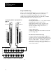
maximum depth dimension per installation will be dependent upon module wiring and connectors.
1771A3B
Side
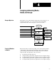
Laying Out the
Backpanel Spacing