
User manual

Understanding Your System
Chapter 1
1-7
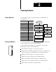
Consider using this technique:
If you are:
SFC
• defining the order of events in a sequential process
Ladder Logic
• more familiar with ladder logic than with programming
languages such as BASIC
• performing diagnostics
• programming discrete control
For detailed information about how you use ladder logic, see your
programming software documentation.
Backup System
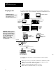
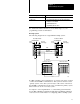
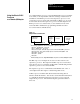
The following diagram shows a typical PLC-5 backup system:
HSSL
1771P4S
Power Supply
1785BCM Module
PLC5
Local I/O Chassis
Local I/O Chassis
Remote I/O Link
DH+ LInk
DH+ Link
18691
Remote I/O Chassis Remote I/O Chassis
Remote I/O Link
Processor
1771P4S
Power Supply
1785BCM Module
PLC5
Processor
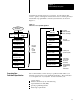
In a PLC-5 backup system configuration, one system controls the operation
of remote I/O and DH+ communications. This system is referred to as the
“primary system.” The other system is ready to take control of the remote
I/O and DH+ communications in the event of a fault in the primary system.
This is referred to as the “secondary system.”
See chapter 2, “Choosing Hardware,” to select backup system hardware.
See the PLC-5 Backup Communication Module User Manual, publication
1785-6.5.4, for more information on configuring a PLC-5 backup system.