
User manual

Design Worksheets
Appendix B
B-17
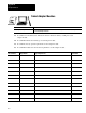
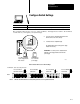
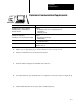
Determine Communication Requirements
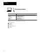
For more information on: See:
Identifying processor connectors/channels
Configuring Channel 0 (serial ASCII port)
Choosing a DH+ link
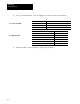
Classic 1785 PLC5 Programmable Controllers User Manual, publication 17856.2.1,
Chapter 5:
Identifying Classic PLC5 Processor Channels/Connectors
Using Channel 0
Configuring a DH+ Link
Selecting DH+ cabling, layout
Selecting processor connectors/channels cabling
Classic 1785 PLC5 Programmable Controllers Design Manual, publication 17856.2.1,
Chapter 3:
Laying Out Your Cable Raceway
Planning Cabling
Selecting termination resistors Classic PLC5 Programmable Controllers Design Manual, publication 17856.2.1, Chapter 2:
Selecting Link Terminators
Defining DH+ station addresses Classic PLC5 Family Programmable Controller Hardware Installation Manual,
publication 17856.6.1
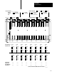
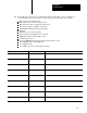
1. Make a copy of appropriate pages of this worksheet for each of your processors.
2. Identify communication modes and network selections.
3. Indicate channel configurations and DH+ station addresses.
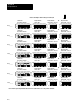
4. List racks attached to each channel/connector configured for remote I/O scanner or adapter mode.
5. Identify DH+ link cable layout (daisy chain or trunkline/dropline).
BOM