
User manual

Design Worksheets
Appendix B
B-15
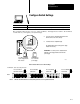
Configure Switch Settings
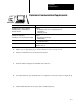
For more information on: See:
Configuring switches Classic PLC5 Programmable Controllers User Manual, publication
17856.2.1, Appendix A
Record switch setting choices on a copy of this worksheet. You might need to return to the worksheet
several times as you complete your system design.
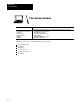
USING
POWER SUPPL
Y
MODULE IN
THE CHASSIS?
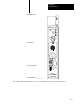
1. Locate the chassis configuration plug (between the
first two left most slots of the chassis).
2. Set the I/O chassis configuration plug.
The default setting is N (not using a power supply
module in the chassis).
NY
NY
NY
Set Y when you install
a power supply module
in the chassis.
Set N when you
use an external
power supply.
IMPORTANT: You cannot power a single I/O chassis
with both a power supply module and an external
power supply.
17075
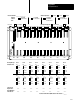
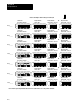
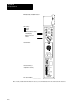
Rack 0 Chassis and Processor Switch Settings
For PLC5/10, 5/12, 5/15, 5/25 processors:
Rack 0
Processor Chassis
Back Plane Switches
Processor Module
Switch SW1
Processor Module
Switch SW2
Processor Module
Switch SW3
OFF
ON
Notes: Switches shown in black are not used, but they must be set to the positions indicated.
ON
ON
12345678
O
N
O
F
F
12345678
O
F
F
O
N
12345678
O
F
F
O
N
123
O
F
F
O
N
4