
User manual
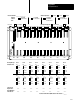
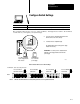
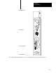

Design Worksheets
Appendix B
B-11
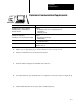
1771A1B
4slot chassis
1771A2B
8slot chassis
1771A3B, or
1771A3B1
12slot chassis
1771A4B
16slot chassis
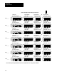
Indicate
Chassis
Size:
R___ R___ R___ R___ R___
R___ R___ R___
Addressing Mode:
2slot 1slot 1/2slotChassis Number: _________________
Processor Complementary I/O?
Yes, chassis______ NoAdapteror
G ___
00-07
10-17
G __
00-07
10-17
Slot 1
G ___
00-07
10-17
G __
00-07
10-17
Slot 2
G ___
00-07
10-17
G __
00-07
10-17
Slot 3
G ___
00-07
10-17
G __
00-07
10-17
Slot 4
G ___
00-07
10-17
G __
00-07
10-17
Slot 5
G ___
00-07
10-17
G __
00-07
10-17
Slot 6
G ___
00-07
10-17
G __
00-07
10-17
Slot 7
G ___
00-07
10-17
G __
00-07
10-17
Slot 8
List Current
Required for
Each Module in
this Chassis:
Identify Groups
and I/O Points:
____
____
____
____
____
____
____
____
____
____
____
____
____
____
____
____
Total Current Draw for I/O Modules in this Chassis = _____
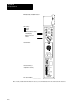
G ___
00-07
10-17
G __
00-07
10-17
Slot 9
G ___
00-07
10-17
G __
00-07
10-17
Slot 10
G ___
00-07
10-17
G __
00-07
10-17
Slot 11
G ___
00-07
10-17
G __
00-07
10-17
Slot 12
G ___
00-07
10-17
G __
00-07
10-17
Slot 13
G ___
00-07
10-17
G __
00-07
10-17
Slot 14
G ___
00-07
10-17
G __
00-07
10-17
Slot 15
G ___
00-07
10-17
G __
00-07
10-17
Slot 16