
User manual


Design Worksheets
Appendix B
B-10
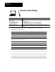
Assign I/O Modules to Chassis and
Assign Addresses
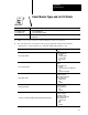
For more information on: See:
Assigning I/O modules to chassis
Selecting addressing mode
Assigning addresses
Addressing complementary I/O
Classic 1785 PLC5 Programmable Controllers User Manual, publication 17856.2.1, Chapter 4:
Placing I/O Modules in Chassis
Choosing the Addressing Mode
Assigning Racks
Addressing Complementary I/O
Selecting the I/O chassis Classic 1785 PLC5 Programmable Controllers Design Manual, publication 17856.2.1, Chapter 2:
Selecting I/O Chassis
Current requirements to I/O modules Automation Products Catalog
,
publication AP 100, Section 3:
Input/Output
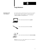
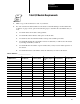
9. Make a copy of the reverse side of this worksheet for each of your chassis, and use it to record
your responses to items 2 through 8.
10. Indicate the addressing mode for each chassis. Use the table below to guide your selection.
If the densest I/O module in the chassis is: And you want to: Then choose:
8point 2slot addressing
16
point
Assign any mix of modules in adjacent module slots 1slot addressing
16point
Make full use of I/O capacity
2slot addressing
32
point
Assign any mix of modules in adjacent module slots 1/2slot addressing
32point
Make full use of I/O capacity 1slot addressing
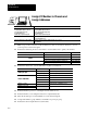
11. Indicate the chassis size. Use the table below to guide your selection.
If you need to: And are: Then consider:
Reduce spare parts
Expanding your system Standard size you now use
Reduce spare parts
Installing a new system
One size using the guidelines listed below
Limited to 9 inches 4slot chassis
Fit space requirements
Limited to 14 inches 8slot chassis
Fit space requirements
Limited to 19 inches
12slot chassis
Limited to 24 inches 16slot chassis
Minimize scan time Largest chassis containing processor
Minimize cost per slot
Largest chassis consistent with decisions above
Accommodate expansion
Largest chassis consistent with decisions above
12. Indicate whether a processor or an adapter is in the left-most slot.
13. Indicate whether you are using this chassis for complementary I/O.
14. Write the module type in each available slot on the chassis diagram.
15. Assign rack numbers, group numbers, and number of points per group.
16. Indicate the current requirement for each module.
BOM