
User manual

Selecting Switch Settings
Appendix A
A-11
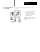
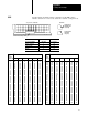
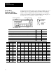
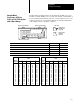
Set SW2 switch assembly switches for an adapter-mode PLC-5 processor
in a PLC-3 or PLC-5/250 processor system. Set switch 2 for the number of
words communicated from the host processor to the adapter processor. Set
switch 3 for I/O group. Set switches 4 through 8 for the I/O rack number
of the adapter processor. Switch 1 is unused.
12345678
1234
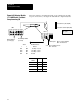
Bottom View of Module
Switch Assembly SW2
Switch Assembly SW3
toggle pushed
on (closed)
toggle pushed
off (open)
Side View
toward bottom
toward top
If you want: Set switch: To:
Switch 1 is always unused. 1 off
The host processor to use 4 words to communicate with the adapter PLC5 processor 2 on
First I/O group to be 0 3 on
First I/O group to be 4 3 off
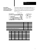
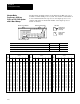
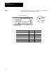
Select the I/O rack number of the adapter PLC5 processor 4 through 8 see below
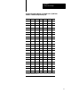
I/O Rack
Number
0
1
2
3
4
5
6
7
10
11
12
13
14
15
16
4
on
on
on
on
on
on
on
on
on
on
on
on
on
on
on
6
on
on
on
on
off
off
off
off
on
on
on
on
off
off
off
5
on
on
on
on
on
on
on
on
off
off
off
off
off
off
off
7
on
on
off
off
on
on
off
off
on
on
off
off
on
on
off
8
on
off
on
off
on
off
on
off
on
off
on
off
on
off
on
Switch
I/O Rack
Number
17
20
21
22
23
24
25
26
27
30
31
32
33
34
35
36
37
4
on
off
off
off
off
off
off
off
off
off
off
off
off
off
off
off
off
6
off
on
on
on
on
off
off
off
off
on
on
on
on
off
off
off
off
5
off
on
on
on
on
on
on
on
on
off
off
off
off
off
off
off
off
7
off
on
on
off
off
on
on
off
off
on
on
off
off
on
on
off
off
8
off
on
off
on
off
on
off
on
off
on
off
on
off
on
off
on
off
Switch
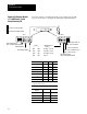
AdapterMode
ProcessorsSW2
in a
PLC3 or PLC5/250 System
with 4Word Groups