
User manual

Selecting Switch Settings
Appendix A
A-8
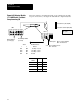
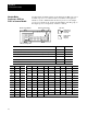
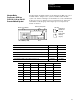
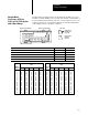
Set SW2 switch assembly switches for an adapter-mode PLC-5 processor
in a PLC-5 processor or scanner module. Set switches 2 through 8 for
number of words communicated from the host processor to the adapter
processor, for the I/O group, and for the rack number of the I/O group of
the adapter processor, respectively. Switch 1 is unused.
12345678
1234
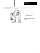
Bottom View of Module
Switch Assembly SW2
Switch Assembly SW3
toggle pushed
on (closed)
toggle pushed
off (open)
Side View
toward bottom
toward top
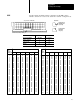
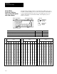
If you want: Set switch: To:
Switch 1 is always unused. 1 off
The host processor to use 8 words to communicate with the adapter PLC5 processor 2 off
The host processor to use 4 words to communicate with the adapter PLC5 processor 2 on
First I/O group to be 0 3 on
First I/O group to be 4 3 off
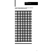
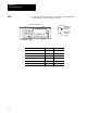
Select the I/O rack number of the adapter PLC5 processor 4 through 8 see table below
Rack 4 5 6 7 8 Rack 4 5 6 7 8
01 on on on on off 15 on off off on off
02 on on on off on 16 on off off off on
03 on on on off off 17 on off off off off
04 on on off on on 20 off on on on on
05 on on off on off 21 off on on on off
06 on on off off on 22 off on on off on
07 on on off off off 23 off on on off off
10 on off on on on 24 off on off on on
11 on off on on off 25 off on off on off
12 on off on off on 26 off on off off on
13 on off on off off 27 off on off off off
14 on off off on on
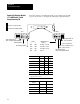
AdapterMode
ProcessorsSW2
in a
PLC5 or Scanner Module