
User manual

Selecting Switch Settings
Appendix A
A-6
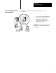
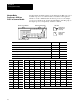
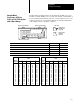
Select the switches to determine I/O rack, group, transmission rate, link
response, and scan for your adapter module using complementary I/O.
ONPrimary Chassis
OFFComplementary Chassis
1234
5678
O
N
O
F
F
SW-1
1234
O
N
O
F
F
SW–2
56
Switch
12
ON
OFF
OFF
ON
OFF
OFF
ON
ON
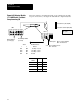
57.6 Kbps10,000 ft
115.2 Kbps5,000 ft
230.4 Kbps2,500 ft
not used
Maximum Chassis
Distance
ONscans for all but 4 last slots
OFFscans for all slots
OFFfor unrestricted
ONPrimary Chassis
OFFComplementary Chassis
I/O Rack Number
First I/O Group Number
Pressed in at top Closed (ON)
Pressed in at bottom Open (OFF)
Link Response: ONfor
series B emulation
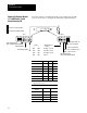
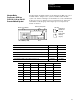
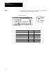
I/O Rack Number
4 5 6
1 on on off
2 on off on
3 on off off
4
1
off on on
5
1
off on off
6
1
off off on
7
1
off off off
1
Valid
for PLC5/25 processors only
. Only seven racks can be
complemented in a PLC5 system.
For First I/O Group
Number
7 8
0 on on
2 on off
4 off on
6 off off
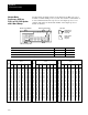
Remote I/O Adapter Module
1771ASB Series C with
Complementary I/O