
User manual

Transferring Discrete and BlockTransfer Data
Chapter 8
8-10
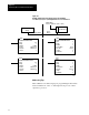
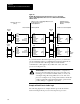
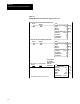
Figure 8.5
Example
Block Transfer from Supervisory Processor to a PLC5/12,
5/15, or 5/25 AdapterMode Processor to Local BlockT
ransfer Module
and V
ice V
ersa
15553
BLOCK TRANSFER WRITE
Rack
Group
Module
Control
2
0
0=LOW
FB001:0000
Data File
Length
FB002:0000
0
BLOCK TRANSFER READ
Rack
Group
Module
Control
2
0
0=LOW
FB001:0000
Data File
Length
FB003:0000
0
BTR
BLOCK TRANSFER READ
Rack
Group
Module
Control Block
3
0
0
N7:10
Data File
Length
N7:100
40
Continuous Y
BLOCK TRANSFER WRITE
Rack
Group
Module
Control Block
3
0
0
N7:20
Data File
Length
N7:150
8
BTW
Continuous Y
BTW
BTR
Data File
FB002
0000
0039
Data File
FB003
0000
0007
Data File
N7
N7:100
N7:139
N7:150
N7:157
//
//
To BT
Module
From BT
Module
Supervisory Processor in Supervisory Processor's
Remote I/O Rack 2
BT Module in Local
I/O Rack 0, I/O Group 2
Module 0
Block Transfers over Remote I/O Link Local BT over chassis backplane
BLOCK TRANSFER WRITE
Rack
Group
Module
Control Block
0
2
0
N7:15
Data File
Length
N7:100
40
Continuous Y
BTW
BLOCK TRANSFER READ
Rack
Group
Module
Control Block
0
2
0
N7:25
Data File
Length
N7:150
8
BTR
Continuous Y
(PLC3)
PLC5/12, 5/15, or 5/25 AdapterMode Processor
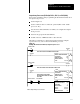
If you block transfer data with a supervisory processor, you cannot use
1/2-slot addressing with a 1771-A4B chassis because the adapter-mode
processor needs the rack 3 I/O image table for block-transfer
communication. (This applies only to PLC-5/12, -5/15, and -5/25
processors in adapter mode.)
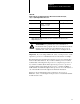
ATTENTION: Do not try block transfers to a supervisory
processor when the adapter-mode processor uses rack 3 for
scanning processor-resident local I/O (when you create your
own adapter image file using a PLC-5/12, -5/15, and -5/25
processor in adapter mode). Using rack 3 addresses under this
condition will result in unpredictable machine operation with
possible damage to equipment or personnel.
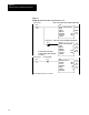
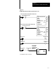
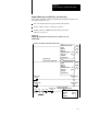
Example of BlockTransfer Ladder Logic
The following figures show example ladder logic for block transfers
between an adapter-mode processor and a supervisory processor.