
User manual

Transferring Discrete and BlockTransfer Data
Chapter 8
8-7
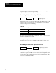
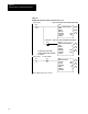
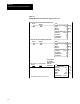
Table 8.L
Status
Bits of the Supervisory Processor Set in the AdapterMode
Processor'
s Data T
able
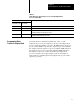
When this bit is set: It indicates that the adaptermode processor:
Rack 3 Input
Image Table (octal)
Adapter Input Image
File (decimal)
10 8 detected a communication failure or received a reset command from the supervisory processor
11 9 received a reset command from the supervisory processor (processor in program or test mode)
13 11 detected that the supervisory processor is powering up; this bit is reset with the first
communication from the supervisory processor
15 13 detected a communication failure (e.g., no communication activity on the remote I/O
communication link within the last 100ms)
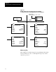
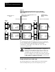
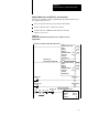
To transfer blocks of data between a PLC-5/12, -5/15, or -5/25
adapter-mode processor and a supervisory processor, the adapter-mode
processor must have a BTW to respond to the BTR from the supervisory
processor (and a BTR to respond to the supervisory processor’s BTW).
For example, when the supervisory processor enables a BTR instruction,
the adapter-mode processor responds by enabling a BTW instruction.
The supervisory processor controls the transfer; the adapter-mode
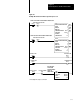
processor responds to the request. Figure 8.4 shows an example of
block-transfer programming between an adapter-mode processor and a
supervisory processor.
Programming Block
Transfer in Adapter Mode