
User manual

Transferring Discrete and BlockTransfer Data
Chapter 8
8-5
Condition the ladder logic in the adapter-mode processor with word 8, bit 8
decimal of the adapter image file. When set, this bit indicates a
communication failure between the adapter and supervisory processors.
ATTENTION: Do not program block transfers to a
supervisory processor if you create an adapter image file.
Transferring Bits between Supervisory and AdapterMode Processors
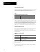
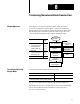
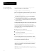
Figure 8.2 shows ladder logic for transferring bit 17 of the supervisory
processor’s output image word 7 and bit 16 of the adapter-mode
processor’s output image word 5. The x represents the adapter-mode
processor’s rack number; rack 3 is the simulated rack for the adapter-mode
processor. This example assumes 1-slot or 2-slot hardware addressing.
Figure 8.2
Transferring
Bits Using Rack 3 in the AdapterMode Processor
17
16
I:37
17
O:35
16
Supervisory Processor (PLC2) Adapter Processor (PLC5)
0x7
Ix5
When the supervisory processor sets its output file bit 0x:7/17, input file bit
I:37/17 in the adapter-mode processor is automatically set. In the same
way, when the adapter-mode processor sets output file bit O:35/16, input
file bit Ix:5/16 in the supervisory processor is automatically set.
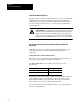
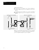
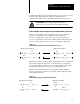
Figure 8.3 shows the ladder logic if you created an adapter image file
because you need rack 3 addresses for local I/O. This example uses N51
as the adapter image file.
Figure 8.3
Transferring
Bits Using Your Own Adapter Image File
17
16
N51:15
15
N51:05
14
Supervisory Processor (PLC2) Adapter Processor (PLC5)
0x7
Ix5