Allen Bradley Classic 1785 PLC 5 Programmable Controllers (1785 LT, LT2, LT3, LT4) User Manual
Important User Information Because of the variety of uses for the products described in this publication, those responsible for the application and use of this control equipment must satisfy themselves that all necessary steps have been taken to assure that each application and use meets all performance and safety requirements, including any applicable laws, regulations, codes, and standards.
Summary of Changes Summary of Changes This manual has been revised to cover only Classic PLC-5 programmable controllers: PLC-5/10, -5/12, -5/15, and -5/25. It has also been revised to include the accompanying design worksheets that were formerly available as a separate publication: 1785-5.2. This separate publication is no longer available; see Appendix B for these worksheets.
Table of Contents Summary of Changes . . . . . . . . . . . . . . . . . . . . . . . . . . . . i Classic PLC 5 Programmable Controllers . . . . . . . . . . . . . iii Purpose of this Manual . . . . . . . . . . . . . . . . . . . . . . . . . . . . . . . . Manual Organization . . . . . . . . . . . . . . . . . . . . . . . . . . . . . . . . . How to Use this Manual . . . . . . . . . . . . . . . . . . . . . . . . . . . . . . . iii iv iv Understanding Your System . . . . . . . . . . . . . . . . . . . . . . .
ii Table of Contents Assigning Addressing Modes, Racks, and Groups . . . . . . 4 1 Chapter Objectives . . . . . . . . . . . . . . . . . . . . . . . . . . . . . . . . . . . Placing I/O Modules in Chassis . . . . . . . . . . . . . . . . . . . . . . . . . . Understanding the Terms Used in this Chapter . . . . . . . . . . . . . . . Choosing the Addressing Mode . . . . . . . . . . . . . . . . . . . . . . . . . . Assigning Racks . . . . . . . . . . . . . . . . . . . . . . . . . . . . . . . . . . . .
Table of Contents iii Calculating Program Timing . . . . . . . . . . . . . . . . . . . . . . . . 9 1 Chapter Objectives . . . . . . . . . . . . . . . . . . . . . . . . . . . . . . . . . . . Introduction to Classic PLC 5 Processor Scanning . . . . . . . . . . . . I/O Scanning Discrete and Block Transfer . . . . . . . . . . . . . . . . . Instruction Timing and Memory Requirements . . . . . . . . . . . . . . . Program Constants . . . . . . . . . . . . . . . . . . . . . . . . . . . . . . . . . .
iv Table of Contents Configure Switch Settings . . . . . . . . . . . . . . . . . . . . . . . . . . . . . . Determine Communication Requirements . . . . . . . . . . . . . . . . . . . Select a Classic PLC 5 Processor . . . . . . . . . . . . . . . . . . . . . . . . Select Power Supplies . . . . . . . . . . . . . . . . . . . . . . . . . . . . . . . . Choose a Programming Terminal . . . . . . . . . . . . . . . . . . . . . . . . . Select Programming Terminal Configuration . . . . . . . . . . . . . . . . .
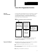
Preface Classic PLC 5 Programmable Controllers How to Use Your Documentation Your Classic PLC-5 Programmable Controllers documentation is organized into manuals according to the tasks you perform. This organization lets you easily find the information you want without reading through information that is not related to your current task. The arrow in Figure 1 points to the book you are currently using.
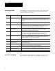
Preface Manual Organization Chapter / Appendix This manual has ten chapters and two appendices. The following table lists each chapter or appendix with its corresponding title and a brief overview of the topics covered in it. Title 1 Understanding Your System Provides an overview of Classic PLC 5 processors in different system configurations. Provides an introduction to Classic PLC 5 processors and their primary features and configurations.
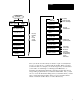
Preface System Design Determined Select I/O modules, terminals Assign addressing Place hardware Configure processor communication Configure Data Highway Plus Select adapter modules Select I/O chassis Select power supply Select PLC 5 processor Select batteries and memory modules Complementary I/O selected? Backup system selected? Assigning Addressing Mode, Racks, and Groups Choosing Hardware and Placing System Hardware Choosing Communication Select programming software Design SFCs Data table layout
Chapter 1 Understanding Your System Using this Chapter Understanding the Terms Used in this Chapter If you want to read about: Go to page: Terms used in this chapter 1 1 Designing systems 1 2 Preparing your functional specification 1 3 Identifying Classic PLC 5 processor features 1 5 Using the Classic PLC 5 processor as a remote I/O scanner 1 8 Using the Classic PLC 5 processor as a remote I/O adapter 1 9 Become familiar with the following terms and their definitions.
Chapter 1 Understanding Your System Designing Systems You can use Classic PLC-5 processors in a system that is designed for centralized control or in a system that is designed for distributed control. HP 9000 or VAX Host Centralized control is a hierarchical system where control over an entire process is concentrated in one processor.
Chapter 1 Understanding Your System Determine the general criteria for your system. Use the chapters that follow to guide you through the criteria and choices for selecting the major Classic PLC-5 programmable controller system elements, as shown in Figure 1.1. Figure 1.
Chapter 1 Understanding Your System Figure 1.2 illustrates a program-development model that you can use. Figure 1.2 Program Development Model Functional Specification (General Conception) Acceptance Sign off Detailed Anaylsis Testing Program Development This model allows for the interaction of activities at the different levels. Each section represents an activity that you perform. Prepare a functional specification to start; then, prepare the detailed analysis.
Chapter 1 Understanding Your System The program-development portion of your functional specification can be in any form: written statement; flowchart; or rough-draft MCPs, SFCs, and subroutines. Use the form that is most familiar to you. We recommend, however, that you generate rough-draft SFCs and subroutines so that you have a better correspondence between your beginning diagrams and your finished program. Detailed Analysis In this phase, you identify the logic needed to plan your programs.
Chapter 1 Understanding Your System Classic PLC 5 Family Processor Features From the family of PLC-5 processors, you can choose the processor(s) that you need for your application.
Chapter 1 Understanding Your System Consider using this technique: If you are: SFC • defining the order of events in a sequential process Ladder Logic • more familiar with ladder logic than with programming languages such as BASIC • performing diagnostics • programming discrete control For detailed information about how you use ladder logic, see your programming software documentation.
Chapter 1 Understanding Your System Using the Classic PLC 5 Processor as a Remote I/O Scanner Use scanner mode whenever you want a Classic PLC-5 processor to scan and control remote I/O link(s). The scanner-mode processor also acts as a supervisory processor for other processors that are in adapter mode. The scanner-mode processor scans the processor memory file to read inputs and control outputs.
Chapter 1 Understanding Your System Using the Classic PLC 5 Processor as a Remote I/O Adapter Use a Classic PLC-5 processor (except the PLC-5/10 processor) in adapter mode when you need predictable, real-time exchange of data between a distributed control PLC-5 processor and a supervisory processor. You connect the processors via the remote I/O link (see Figure 1.3). You can monitor status between the supervisory processor and the adapter-mode PLC-5 processor at a consistent rate (i.e.
Chapter 2 Choosing Hardware Chapter Objectives Use this chapter to guide you in the selection of system hardware for your application.
Chapter 2 Choosing Hardware Table 2.A Guidelines for Selecting I/O Modules Choose this type of I/O module: For these types of field devices or operations (examples): Explanation: Discrete input module and block I/O module1 Selector switches, pushbuttons, photoelectric eyes, limit switches, circuit breakers, proximity switches, level switches, motor starter contacts, relay contacts, thumbwheel switches Input modules sense ON/OFF or OPENED/ CLOSED signals. Discrete signals can be either ac or dc.
Chapter 2 Choosing Hardware Master/Expander I/O Modules Some I/O modules (called “masters”) communicate with their expanders over the backplane. These master/expander combinations either: can time-share the backplane, or cannot time-share the backplane For masters that can time-share the backplane, you can use two masters in the same chassis. For a master/expander combination that cannot time-share the backplane, you cannot put another master/expander combination in the same I/O chassis.
Chapter 2 Choosing Hardware Selecting I/O Adapter Modules Select I/O adapter modules to interface your PLC-5 processor with I/O modules. Use Table 2.D as a guide when you select I/O adapter modules. Table 2.D Guidelines for Selecting Adapter Modules ASB ALX Choose: When your requirements are: 1771 AS or 1771 ASB1 Remote I/O Adapter Module (or 1771 AM1, AM2 chassis with integral power supply and adapter module) a remote I/O link with: • 57.
Chapter 2 Choosing Hardware 1771 ALX Extended Local I/O Adapter Module Table 2.F shows the I/O density per module and addressing modes you can use with I/O chassis and extended-local I/O adapter modules. Table 2.F I/O Chassis/Extended Local I/O Adapter Module Combinations Module Cat. Cat No No.
Chapter 2 Choosing Hardware Selecting I/O Chassis An I/O chassis is a single, compact enclosure for the processor, power-supply modules, remote and extended-local I/O adapter modules, and I/O modules. The left-most slot of the I/O chassis is reserved for the processor or adapter module.
Chapter 2 Choosing Hardware Table 2.G Guidelines for Selecting an Operator Interface Choose this operator interface: For these types of operations (examples): Explanation: PanelView1 Starts/stops, auto/manual operations, Used as an operator window to enter commands that make process adjustments such setpoints, outputs, alarms as starts/stops and loop changes. Can also be used for alarming operations. Can communicate with a single PLC 5 processor on a remote I/O link.
Chapter 2 Choosing Hardware For more information on selecting and configuring PanelView, see: PanelView Operator Terminal and PanelBuilder Development Software User Manual, cat. no. 2711-ND002 version C, PN40061-139-01— request latest revision Replacing Node Adapter Firmware for PanelView Terminals Installation Data, PN40062-236-01—request latest revision For more information on selecting and configuring ControlView, see: ControlView Core User Manual, publication 6190-6.5.
Chapter 2 Choosing Hardware Choosing a Classic PLC 5 Processor for Your Application Processor/ Cat. No. PLC 5/10 (1785 LT4) PLC 5/12 (1785 LT3) Maximum User Memory Words 6K 6K PLC 5/15 (1785 LT) 6 K expandable to 10 K or 14 K PLC 5/25 (1785 LT2) 13 K expandable to 17 K or 21 K Choose from the following PLC-5 processors. Table 2.
Chapter 2 Choosing Hardware 3. 4. 5. Add to the total of the I/O module backplane current draw either: a. 3.3 Amps when the chassis will contain a PLC-5 processor (maximum current draw for any PLC-5 processor) or b. 1.2 Amps when the chassis will contain either a remote I/O 1771-AS or -ASB module or a 1771-ALX extended-local I/O adapter module If you leave slots available in your chassis for future expansion: a. list backplane current draw for future I/O modules b.
Chapter 2 Choosing Hardware Table 2.
Chapter 2 Choosing Hardware Powering a Remote I/O Chassis Containing a 1771 AS or 1771 ASB or an Extended Local I/O Chassis Containing a 1771 ALX Table 2.L lists the power supply modules that you can use with a remote I/O chassis or an extended-local I/O chassis. Table 2.
Chapter 2 Choosing Hardware Selecting Memory Modules Select a memory module from Table 2.M for your PLC-5 processor. Table 2.M PLC 5 Processor Memory Modules Nonvolatile Memory Backup (EEPROM) Selecting a Replacement Battery RAM Memory (CMOS) Words Catalog Number (and Processor) Words Catalog Number (and Processor) 8K 1785 MJ 4K 1785 MR (PLC 5/15 and 5/25) 16 K 1785 MK (PLC 5/25) 8K 1785 MS (PLC 5/15 and 5/25) A battery ships with your PLC-5 processor.
Chapter 2 Choosing Hardware Use the following modules in either primary or complementary I/O chassis opposite any type of module: Communication Adapter Module (1771-KA2) Communication Controller Module (1771-KE) PLC-2 Family/RS-232-C Interface Module (1771-KG) Fiber Optics Converter Module (1771-AF) DH/DH+ Communication Adapter Module (1785-KA) DH+/RS-232C Communications Interface Module (1785-KE) Use the following modules in either primary or complementary I/O chassis opposite any type of module.
Chapter 2 Choosing Hardware Selecting Link Terminators Terminate remote I/O links by setting switch assembly SW3. If you cannot use an 82-Ohm terminator because of devices that you place on your I/O link (see the table below for a list of these devices), you must use 150-Ohm terminators. Using the higher resistance reduces the quantity of devices to 16 that you can place per remote I/O link. Also, this limits your communication rates to 57.6 kbps and 115.2 kbps.
Chapter 2 Choosing Hardware See the Classic 1785 PLC-5 Programmable Controllers Hardware Installation Manual, publication 1785-6.6.1, and the installation data for the I/O modules that you have selected for more information on I/O wiring. Also, see Allen-Bradley Programmable Controller Wiring and Grounding Guidelines, publication 1770-4.1, and Control, Communication and Information Reference Guide, publication ICCG-1.2, for more information.
Chapter 3 Placing System Hardware Chapter Objectives A well-planned layout is essential to the proper installation of your Classic PLC-5 programmable controller system. Read this chapter for information on placing hardware.
Chapter 3 Placing System Hardware To allow for proper convection cooling in enclosures containing a processor-resident chassis and remote I/O chassis, follow these guidelines. Minimum spacing requirements for a processor resident chassis: • Mount the I/O chassis horizontally. Area reserved for disconnect. transform er, control relays, m otor starters or other user devices. • Allow 153 mm (6 in) above and below the chassis. • Allow 102 mm (4 in) on the sides of each chassis.
Chapter 3 Placing System Hardware Minimum spacing requirements for a remote I/O chassis: Area reserved for disconnect. transformer, control relays, mo t o r starters or other user devices. 102mm (4") 153mm (6") 153mm (6 ") • Allow 153 mm (6 in) above and below all chassis. When you use more than one chassis in the same area, allow 152.4 mm (6 in) between each chassis. • Allow 102 mm (4 in) on the sides of each chassis. When you use more than one chassis in the same area, allow 101.
Chapter 3 Placing System Hardware Protecting Your Processor You provide the enclosure for your processor system. This enclosure protects your processor system from atmospheric contaminants such as oil, moisture, dust, corrosive vapors, or other harmful airborne substances. To help guard against EMI/RFI, we recommend a steel enclosure. Mount the enclosure in a position where you can fully open the doors. You need easy access to processor wiring and related components so that troubleshooting is convenient.
Chapter 3 Placing System Hardware To plan a raceway layout, do the following: categorize conductor cables route conductor cables Categorize Conductors Segregate all wires and cables into categories as described in the Industrial Automation Wiring and Grounding Guidelines, publication 1770-4.1. See the installation data for each I/O module that you are using for information about its classification.
Chapter 3 Placing System Hardware Laying Out the Backpanel Spacing Use 6.35 mm (0.25 inch) mounting bolts to attach the I/O chassis to the enclosure backpanel. Figure 3.1 Chassis Dimensions (Series B) 1771 A1B 1771 A2B 1771 A3B1 1771 A4B 591mm (23.25") 337mm (13.25") 193mm1 (7.60") Side 464mm (18.25") 210mm (8.25") 315mm (12.41") 16 slot 1771 12 slot 8 slot 4 slot 254mm (10") Power Connector 171mm (6.75") 483mm (19.01") 229mm (9.01") 1771 A3B 217mm1 (8.54") 465mm (18.31") 610mm (24.
Chapter 3 Placing System Hardware Figure 3.2 I/O Chassis and 1771 P2 Power Supply Dimensions Use .25" dia mounting bolts (4 places) 315mm (12.41") 591mm (23.25") 16-slot 464mm (18.25") 337mm (13.25") 12-slot 8-slot 210mm (8.25") 4-slot 1771 P1 1771 P2 1771 P7 1771 PS7 Power Supply 91mm (3.6") 254mm (10") 483mm (19.01") 610mm (24.01") 16-slot 1771-A4B 12-slot 1771-A3B1 356mm (14.01") 229mm (9.01") Clearance depth is 204 mm (8 in) for 8 I/O connection points per module.
Chapter 4 Assigning Addressing Modes, Racks, and Groups Chapter Objectives This chapter conveys basic hardware addressing concepts and gives you guidelines with which to choose the addressing modes (including complementary I/O), racks, and groups to use in your system.
Chapter 4 Assigning Addressing Modes, Racks, and Groups The following guidelines are for placing block-transfer modules. Place as many modules as possible for which you need fast block-transfer times in your processor-resident local I/O chassis . Place modules that need fast block-transfer times (but space is not available in processor-resident local I/O chassis) in an extended-local I/O chassis. Place modules in which timing is not as critical as in other block-transfer modules in remote I/O chassis.
Chapter 4 Assigning Addressing Modes, Racks, and Groups An I/O rack is an addressing unit that corresponds to 8 input image-table words and 8 output image-table words. A rack contains 8 I/O groups. I/O Group Numbers . 0 1 2 3 4 5 6 7 13074 Depending on I/O chassis size and I/O group size, an I/O rack can occupy a fraction of an I/O chassis, a full I/O chassis, or multiple I/O chassis.
Chapter 4 Assigning Addressing Modes, Racks, and Groups 8-Point I/O Modules Eight-point digital discrete I/O modules have a maximum of eight inputs or up to eight outputs. Because they do not interfere with each other’s I/O image, you can place any mix of 8-point I/O modules (including bidirectional modules, such as block-transfer modules) in any order.
Chapter 4 Assigning Addressing Modes, Racks, and Groups 16-Point I/O Modules Sixteen-point digital discrete I/O modules have up to 16 inputs or up to 16 outputs. A 16-point I/O module uses a full word in the input or output image table.
Chapter 4 Assigning Addressing Modes, Racks, and Groups Using 1 Slot Addressing When you select 1-slot addressing, the processor addresses one I/O module slot as one I/O group. Each physical slot in the chassis corresponds to an input and output image-table word. The type (unidirectional or bidirectional) and density of module that you install determines the number of bits used in these words.
Chapter 4 Assigning Addressing Modes, Racks, and Groups 32-Point I/O Modules To use 32-point I/O modules with 1-slot addressing, you must install, as a pair, an input module and an output module in two adjacent slots (even/odd pair) of the I/O chassis, beginning with I/O slot 0. If you cannot pair the modules in this way, one of the two slots of the pair must be empty.
Chapter 4 Assigning Addressing Modes, Racks, and Groups Using 1/2 Slot Addressing When you select 1/2-slot addressing, the processor addresses one-half of an I/O module slot as one I/O group. Each physical slot in the chassis corresponds to two input and two output image-table words. The type (unidirectional or bidirectional) and density of the module that you install determines the number of bits that are used in each word.
Chapter 4 Assigning Addressing Modes, Racks, and Groups Summary Table 4.A summarizes the guidelines for selecting an addressing mode. Table 4.
Chapter 4 Assigning Addressing Modes, Racks, and Groups When assigning rack numbers, use the following guidelines: One I/O rack number is eight I/O groups, regardless of the addressing mode that you select. You can assign from one to four racks in your processor-resident local chassis (128 inputs and 128 outputs) depending on the chassis size and addressing mode.
Chapter 4 Assigning Addressing Modes, Racks, and Groups When assigning remote I/O rack numbers, use the following guidelines: Limit the number of remote I/O rack numbers to those that your PLC-5 processor can support. The PLC-5 processor and the 1771-ASB adapter module automatically allocate the next higher rack number(s) to the remaining I/O groups of the chassis.
Chapter 4 Assigning Addressing Modes, Racks, and Groups Addressing Complementary I/O You configure complementary I/O by assigning an I/O rack number of one I/O chassis (primary) to another I/O chassis (complementary), complementing modules I/O group for I/O group. The I/O modules in the complementary chassis perform the opposite function of the corresponding modules in the primary chassis. The PLC-5/15 and -5/25 processors operating as a remote I/O scanner support complementary I/O.
Chapter 4 Assigning Addressing Modes, Racks, and Groups Figure 4.
Chapter 4 Assigning Addressing Modes, Racks, and Groups Placing the Modules with 1 Slot Addressing Figure 4.6 shows a possible module placement to configure complementary I/O using 1-slot addressing. Figure 4.
Chapter 4 Assigning Addressing Modes, Racks, and Groups Placing the Modules with 1/2 Slot Addressing Figure 4.7 shows a possible module placement to configure complementary I/O using 1/2-slot addressing. Figure 4.
Chapter 4 Assigning Addressing Modes, Racks, and Groups Placing Complementary I/O Modules See Table 4.B for a summary of 8-, 16-, and 32-point I/O module placement guidelines. See Table 4.C for a summary of block-transfer module placement guidelines. Table 4.
Chapter 5 Choosing Communication Chapter Objectives Use this chapter to choose the appropriate communication for your application.
Chapter 5 Choosing Communication Figure 5.
Chapter 5 Choosing Communication Configuring Communication for Your Processor You select scanner or adapter mode for your PLC-5 processor by setting switches. Configure Processor Communication You configure the processor by setting switch assemblies SW1 and SW2 on the processor. See Appendix A for information on switch settings. Follow these steps to plan configuration for your processor. 1. Select scanner or adapter mode on switch assembly SW1 (the PLC-5/10 and -5/12 can not be configured as scanners).
Chapter 5 Choosing Communication Nodes Nodes affect transmission time in the following ways: During one complete token rotation, each node on the DH+ link receives the token whether or not it has something to send. Each node spends from 1.5 ms (if it has no messages to send) to 38 ms (maximum time allotted) with the token, assuming there are no retries (Figure 5.2). Figure 5.2 Token Passing Min. 1.5 ms with the token Station 1 Station 5 DH+ link Station 2 Station 4 Station 3 Max.
Chapter 5 Choosing Communication Message Destination Throughput times vary depending on whether a receiving station can process the message and generate a reply before that station receives the token. Figure 5.3 assumes that station 1 wants to send a message to station 4. Figure 5.3 Message Destination Example 1 Station 1 Station 5 Station 2 Message Station 4 Station 1 has the token. Only the station that has the token can send a message. Station 1 sends the message to station 4.
Chapter 5 Choosing Communication In Figure 5.4, we assume that station 1 wants to send the identical message as shown in Figure 5.3 but to station 2. Station 1 has the token. Station 1 sends the message to station 2 and then passes the token on to station 2. Now station 2 has the token but has not had time to generate a reply to station 1. So station 2 sends any other messages it has queued and then passes the token on to station 4.
Chapter 5 Choosing Communication Figure 5.5 Average Response Time for all PLC 5 Processors 5.0 4.5 4.0 3.5 Response Time (Sec) 3.0 50 W 2.5 2.0 • 100 W 1.5 + 250 W 1.0 X 500 W 0.5 0.0 W=Words 1 2 3 4 5 6 7 8 9 10 11 12 13 14 Number of PLC 5 Processors 15 16 17 18 19 20 21 22 Figure 5.6 shows the effect of a programming terminal on message response time under various configurations. Figure 5.
Chapter 5 Choosing Communication Initial testing was done with one PLC-5 processor writing data to another PLC-5 processor. The response time was recorded. Additional PLC-5 processors were added to the network, each writing the same amount of data to a PLC-5 processor at the next highest station address. Four separate tests were run using data transmissions of 50, 100, 250, and 500 words. Application Guidelines Consider the following application guidelines when configuring a DH+ link for your system.
Chapter 5 Choosing Communication Figure 5.7 Examples of DH+ Link Connections (Daisy Chain and Trunkline/Dropline) PLC 5 PLC 5 PLC 5 PLC 5 1 SH 2 T50 When the processor is an end device, terminate the link. Daisy chain configuration Station connector (see notes) PLC 5 PLC 5 PLC 5 Notes: T50 Trunkline/dropline configuration Once a programming terminal is connected to one processor, it can communicate with each processor you connect on DH+. Use only Allen Bradley station connectors.
Chapter 5 Choosing Communication The PLC-5 processor has two connectors that are electrically identical. Connection to either one provides the same communication link. These connectors are: 9-pin D-shell DH+ COMM INTFC connector 3-pin DH+ COMM INTFC connector Connecting a DH+ Link to Data Highway You can connect DH+ links to Data Highway via a communication interface such as the 1785-KA module. The 1785-KA module allows nodes on a DH+ link to communicate with nodes on Data Highway or on another DH+ link.
Chapter 5 Choosing Communication Figure 5.8 Connection to DH+ Link through 1784 KT Communication Interface Module DH+ link 1784 CP T53 or IBM compatible with 1784 KT PLC 5/10, 5/12 5/15, or 5/25 processor Use a 1784-KL/B to connect a T47 programming terminal directly to a processor or to a DH+ link that connects processors (Figure 5.9). Figure 5.
Chapter 5 Choosing Communication Figure 5.
Chapter 5 Choosing Communication Figure 5.11 1785 KE (Series B) Connection through an RS 232 C Serial Port DH+ link T53 serial port COM1 or COM2 1785 KE Series B PLC 5/10, 5/12, 5/15, or 5/25 processor Figure 5.
Chapter 6 Planning Your System Programs Chapter Objectives This chapter covers basic programming considerations for planning a Classic PLC-5 programmable controller system.
Chapter 6 Planning Your System Programs 002 Initial Step 003 005 004 006 008 007 009 010 011 012 013 014 015 Each step corresponds to a control task (displayed as a box); each step is related to a program file that contains the logic for the associated control task. Each transition (displayed as a horizontal line) examines conditions, specified in an associated program file, that determines when the processor can continue to the next task.
Chapter 6 Planning Your System Programs Application Example for SFCs For typical SFC applications, an SFC program controls the order of events in your process by issuing commands. A command, such as fwdcyr_cmd to move a conveyor forward, is simply a data table storage bit (for example B3:0/7) that you set up in the SFC. You then program the logic for fwdcyr_cmd in a separate ladder program to control the actual outputs to move the conveyor.
Chapter 6 Planning Your System Programs Organizing a Machine Example This section uses an example of a specific machine operation to show how to identify conditions and actions and how to group the actions into steps of machine operation. Figure 6.1 Hardware Block Diagram and Description of Machine Process L oad S t a t i on O FF AUTO FW D FW D C onveyor M otor FW D A dvance A ssem bly D rill M oto r C lam p LS 1 N . O. N . C . LS 2 C L1 LS 3 N. O. H e ld O pen N. O. LS 4 LS 5 N . O.
Chapter 6 Planning Your System Programs We recommend that you then create a rough-draft SFC to represent the operation (see Figure 6.2). Figure 6.
Chapter 6 Planning Your System Programs Table 6.C Hardware Requirements for the Inputs and Output of the Drill Example Input Part Description AUTO selector switch select automatic mode LS1 N.O. limit switch part in place LS2 N.C. limit switch drill station home LS3 N.O. limit switch drill motor on LS4 N.O. limit switch drill station at full depth LS5 N.O.
Chapter 6 Planning Your System Programs Once you identify the individual actions, you can add these actions to your plan to complete your program. Once you have an SFC program that defines the individual machine actions for your process, you can create a ladder-logic program that controls the outputs of those machine actions. It does not matter in what order you program these rungs. This program merely contains the ladder logic that defines a command for each machine action in your process.
Chapter 6 Planning Your System Programs Table 6.
Chapter 6 Planning Your System Programs Data Table Addressing Formats Address Type Description Example Logical address Alpha numeric coded format to specify the data location N23:0 addresses an integer file 23, word 0 I/O image address Logical address format, but relates physical locations in the I/O chassis to memory locations in the I/O image file I:017/17 addresses input file word 017 (octal), bit 17 (octal), which corresponds to rack 01, module group 7, and terminal 17 Indirect address Logica
Chapter 6 Planning Your System Programs Table 6.
Chapter 6 Planning Your System Programs This word of the status file: S:28 S:29 S:30 S:31 Stores: Program watchdog setpoint (in ms) Fault routine file STI setpoint (in ms) STI file number 6-11
Chapter 7 Selecting Interrupt Routines Chapter Objectives This chapter covers interrupt routines that you can choose to include when you program your system.
Chapter 7 Selecting Interrupt Routines Program Execution States User programs in the Classic PLC-5 processor are always in one of the following five states: completed, ready, executing, waiting, or faulted.
Chapter 7 Selecting Interrupt Routines Writing a Fault Routine You can write a fault routine that the processor runs when it detects a major fault. For example, if your program file becomes corrupted, you can tell the processor to interrupt the current program, run your fault routine and then continue processing the original program. This section shows you how to set and write a fault routine and how to protect your processor from powering up in run mode after a power loss.
Chapter 7 Selecting Interrupt Routines Table 7.
Chapter 7 Selecting Interrupt Routines Table 7.
Chapter 7 Selecting Interrupt Routines Important: If the PLC-5 processor detects a fault in the fault routine (double fault condition), the PLC-5 processor goes directly to fault mode without completing the fault routine.
Chapter 7 Selecting Interrupt Routines In Figure 7.4, #N10:0 is the reference file. Figure 7.4 Example of Comparing a Major Fault Code with a Reference R6:0 RES R6:0 U IN FSC FILE SEARCH/COMPARE EN Control R6:0 Length 20 Position 0 Mode Expression S:12 = #N10:0 R6:0 ] [ MOV FD Source DN ALL ER MOVE Dest 0 S:11 10 JMP Last rung in fault routine 10 ] LBL [ TND The processor completes the scan of the fault routine.
Chapter 7 Selecting Interrupt Routines Using Shutdown Logic Shutdown programming should include the following considerations. Store initial conditions and reset other data to achieve an orderly start-up later. Monitor the shutdown of critical outputs. Use looping if needed to extend the single fault routine scan time up to the limit of the processor watchdog timer so that your program can confirm that critical events took place.
Chapter 7 Selecting Interrupt Routines If you do not specify a program file number, the processor immediately enters fault mode after detecting a fault. Changing the Fault Routine File Number from Ladder Logic You can change the specified fault routine from ladder logic by copying a new fault routine file number into word 29 of the processor status file. Figure 7.5 shows an example program for changing the fault routine file number. Figure 7.
Chapter 7 Selecting Interrupt Routines Setting Power Up Protection You can set your processor so that after a power loss the processor does not come up in run mode. Bit 1 in word 26 of the processor status file sets power-up protection. Table 7.I shows the states for this bit. Table 7.
Chapter 7 Selecting Interrupt Routines Understanding Processor Detected Major Faults In general, if the processor detects a hardware fault, it sets a major fault and resets I/O. If the processor detects a run-time error, it sets a major fault bit and the remote I/O racks are set according to their last state switch. Module outputs in remote racks remain in their last state or they are de-energized, based on how you set the last state switch in the 1771 I/O chassis.
Chapter 7 Selecting Interrupt Routines Fault in a Remote I/O Chassis In general, when a remote I/O chassis faults, the processor sets an I/O rack fault bit and then continues scanning the program and controlling the remaining I/O. The outputs in the faulted rack remain in their last state or they are de-energized, based on how you set the last state switch in the 1771 I/O chassis.
Chapter 7 Selecting Interrupt Routines The I/O rack status bits, also known as the “partial rack status bits,” are used to monitor the racks in your I/O system. The software automatically creates an integer data file to store this information when an I/O status file is defined. This file contains 2 words of status bits for every rack configured in your system. The number of the data file that contains this I/O information is stored in word 16 (low byte) of the status file.
Chapter 8 Transferring Discrete and Block Transfer Data Chapter Objectives This chapter covers discrete and block transfer of I/O data when a processor is configured for either adapter or scanner mode. Discretetransfer data are words transferred to/from a digital discrete I/O module. Block-transfer data is transferred, in blocks of data of up to 64 words, to/from a block-transfer I/O module (such as an analog module).
Chapter 8 Transferring Discrete and Block Transfer Data During each remote I/O scan: the supervisory processor transfers 2, 4, 6 or 8 words—depending on whether the adapter-mode processor is configured as a 1/4, 1/2, 3/4 or full rack the adapter-mode processor transfers 2, 4, 6 or 8 words—depending on whether the adapter-mode processor is configured as a 1/4, 1/2, 3/4 or full rack Supervisory Processor in Scanner Mode PLC 5 Processor in Adapter Mode Remote I/O Buffer Read Inputs Write Outputs Data Exch
Chapter 8 Transferring Discrete and Block Transfer Data Figure 8.
Chapter 8 Transferring Discrete and Block Transfer Data Programming Discrete Transfer in Adapter Mode For the supervisory processor, use the adapter’s configured I/O rack number to receive data or store data for transfer. Using Rack 3 (Addresses 0:30 0:37 and I:30 I:37) Rack 3 is the default discrete-transfer file for PLC-5/12, -5/15, and -5/25 processors. Typically, each output instruction in one processor should have a corresponding input instruction in the other processor.
Chapter 8 Transferring Discrete and Block Transfer Data Condition the ladder logic in the adapter-mode processor with word 8, bit 8 decimal of the adapter image file. When set, this bit indicates a communication failure between the adapter and supervisory processors. ATTENTION: Do not program block transfers to a supervisory processor if you create an adapter image file. Transferring Bits between Supervisory and Adapter Mode Processors Figure 8.
Chapter 8 Transferring Discrete and Block Transfer Data For PLC-5/12, -5/15, and -5/25 processors, words 0-7 in the integer file represent output, words 8-15 represent input. Determining the Status of the Adapter Mode Processor Supervisor Adapter Adapter mode processor sends to Supervisory processor The supervisory processor receives these status bits (Table 8.K) from the adapter-mode processor in word 0 of the input file for the rack that the adapter-mode processor is emulating. Table 8.
Chapter 8 Transferring Discrete and Block Transfer Data Table 8.
Chapter 8 Transferring Discrete and Block Transfer Data Figure 8.
Chapter 8 Transferring Discrete and Block Transfer Data Table 8.
Chapter 8 Transferring Discrete and Block Transfer Data Figure 8.
Chapter 8 Transferring Discrete and Block Transfer Data Supervisory Processor (PLC 2/30, PLC 3, PLC 5, or PLC 5/250) Follow these guidelines when programming block-transfer instructions in the supervisory processor. Set the length to 0. Set the continuous bit for continuous operation (PLC-5 and -5/250 processors only). Use the remote I/O rack number for which you configure the adaptermode processor. Use 0 for the group and module numbers. Condition the use of BTR data with a “data valid” bit.
Chapter 8 Transferring Discrete and Block Transfer Data Figure 8.
Chapter 8 Transferring Discrete and Block Transfer Data Figure 8.
Chapter 8 Transferring Discrete and Block Transfer Data Figure 8.
Chapter 8 Transferring Discrete and Block Transfer Data Adapter Mode Processor (PLC 5/12, 5/15, and 5/25) Follow these guidelines when programming block-transfer instructions in the adapter-mode processor. Use 3 for the rack, 0 for the group, and 0 for the module. Set the continuous bit for continuous operation. Condition the use of BTR data with status bits from the supervisory processor. Figure 8.
Chapter 8 Transferring Discrete and Block Transfer Data Transferring Data Using Scanner Mode A PLC-5 processor, in scanner mode, transfers discrete-transfer and block-transfer data with processor-resident local and remote I/O chassis. If you have your processor configured for scanner mode, refer to the following sections for more information on how a PLC-5 processor transfers data in scanner mode.
Chapter 8 Transferring Discrete and Block Transfer Data Programming Block Transfer in Scanner Mode The processor block transfers data to and from its processor-resident local and remote I/O chassis when operating in scanner mode. The processor performs block transfers asynchronously to the program scan. The processor also interrupts the program scan asynchronously to momentarily access BTW and BTR data files.
Chapter 8 Transferring Discrete and Block Transfer Data Block Transfers of Remote I/O Data Block transfers of I/O data to remote I/O follow these procedures. block-transfer requests are queued for each addressed remote I/O rack Each active buffer transfers one data block per remote I/O scan. The processor momentarily interrupts program scan when the active buffer performs a block-transfer request to access the block-transfer data file.
Chapter 8 Transferring Discrete and Block Transfer Data Block Transfer Sequence Figure 8.11 shows the sequence the processor follows to run a block transfer. Figure 8.11 Block Transfer Sequence 1, 7 Ladder Program 6 STI Data Files 2 Q17 Buffer for 17 BT Requests Request Priority Request 3a, 3b, 5 Active BT area Data Data Acknowledgement and Incoming Data Request and Outgoing Data 4a, 4b I/O Chassis 1. Ladder logic enables the block transfer. 2.
Chapter 8 Transferring Discrete and Block Transfer Data Block Transfer Sequence with Status Bits The following explanations describe how the ladder logic and the I/O scanner handle block transfers with status bits: Ladder logic: detects that the rung containing a block transfer is enabled sets the enable .EN bit (15) detects the status of the read/write .RW bit (07) places the block transfer in the active buffer if the queue is empty; the processor sets the start .
Chapter 8 Transferring Discrete and Block Transfer Data Programming Considerations In a distributed control system where your process is controlled by several independent programmable controllers, make sure that your program considers the status of the PLC processors and the integrity of the communication link by using the status bits that the supervisory and adapter mode processor provide for each other.
Chapter 8 Transferring Discrete and Block Transfer Data Considerations for Processor Resident Local Racks The following are programming considerations when you are blocktransferring data in a processor-resident local rack. Within the processor-resident local rack, limit the number of continuous-read block transfers to 16 transfers of 4 words each or 8 transfers of 64 words each. If you attempt to exceed this block-transfer limit, a checksum error (error code -5) occurs.
Chapter 9 Calculating Program Timing Chapter Objectives This chapter provides information to help you determine the program timing for your PLC-5 programmable controller system.
Chapter 9 Calculating Program Timing processor internal checks updating the input image table with processor-resident I/O input status updating processor-resident local I/O output modules with data from the output image table updating the input image table with remote I/O input status as contained in the remote I/O buffer updating the remote I/O buffer with output data from the output image table If no change in input status occurs and the processor continues to execute the same logic instructions, the pro
Chapter 9 Calculating Program Timing Effects of Different Input States on Logic Scan Time You can write your logic so that it executes different rungs at different times, based on input conditions. The different amounts of logic executed in the logic scans causes differences in program scan times. For example, the simple differences in rung execution in the following example cause the logic scan times to vary.
Chapter 9 Calculating Program Timing I/O placed in the same chassis as the processor is called “processorresident” local I/O. These inputs and outputs are not updated during the remote I/O scan—they are updated during the housekeeping portion of the program scan. During housekeeping, the processor reads and writes the I/O across the chassis backplane. Thus, the update of processor-resident local I/O is synchronous to the program scan. Figure 9.
Chapter 9 Calculating Program Timing I/O Scanning Discrete and Block Transfer A Classic PLC-5 processor can transfer discrete data and block data to/from processor-resident local I/O, extended-local I/O chassis, and remote I/O chassis. Transferring Discrete Data The remote I/O system is scanned in a separate and asynchronous scan to the program scan. The remote I/O scan takes output data from the remote I/O buffer to output modules and puts input data into the remote I/O buffer from input modules.
Chapter 9 Calculating Program Timing Remote I/O and Processor-Resident I/O The processor performs block transfers asynchronously to the program scan. The processor also interrupts the program scan asynchronously to momentarily access BTW and BTR data files. The processor performs one remote block transfer per addressed rack and per remote I/O scan. Figure 9.2 shows timing loops for block transfer from a Classic PLC-5 processor. Figure 9.
Chapter 9 Calculating Program Timing Instruction Timing and Memory Requirements The time it takes for a processor to scan an instruction depends on the type of instruction, the type of addressing, the type of data, whether the instruction has to convert data, and whether the instruction is true or false.
Chapter 9 Calculating Program Timing Bit and Word Instructions for PLC 5/10, 5/12, 5/15, and 5/25 Processors Table 9.N shows timing and memory requirements for bit and word instructions for PLC-5/10, -5/12, -5/15, and -5/25 processors. Table 9.N Timing and Memory Requirements for Bit and Word Instructions for PLC 5/10, 5/12, 5/15, and 5/25 Processors Category Relay Code Title Execution Time (µs) Integer Execution Time (µs) Floating Point True False True 1.3 0.
Chapter 9 Calculating Program Timing Category Arithmetic Logic Move Comparison Code Title Execution Time (µs) Integer Execution Time (µs) Floating Point True False True False 36 14 92 14 4 7 14 3 5 14 2 3 Words of Memory2 ADD add SUB subtract MUL multiply 41 14 98 DIV divide 49 14 172 SQR square root 82 14 212 NEG negate 28 14 36 CLE clear 18 14 23 TOD convert to BCD 52 14 3 5 FRD convert from BCD 44 AND and 36 14 4 7 OR or XOR exclusive o
Chapter 9 Calculating Program Timing Category Compute Code CPT Execution Time (µs) Integer Execution Time (µs) Floating Point True False True False 67 34 124 34 6 9 multiply 73 34 130 divide 80 34 204 square root 113 33 244 34 5 7 negate 59 33 68 clear 49 30 55 34 4 5 move 58 33 5 7 convert to BCD 84 convert from BCD 75 AND 68 34 6 9 NOT 59 34 5 7 equal 63 34 Title add Words of Memory2 subtract OR XOR Compare CMP 73 not equal less than less
Chapter 9 Calculating Program Timing File Instructions The instruction timing for file instructions depends on the data type, number of files acted on per scan, number of elements acted on per scan, and whether the instruction converts data between integer and floating point formats. Table 9.O shows PLC-5/10, -5/12, -5/15, and -5/25 processors.
Chapter 9 Calculating Program Timing Category File Shift Register Diagnostic Code Title Time (µs) Integer or Floating Point True True False copy counter, timer, and control 88 + 2.7W 98 + 5.8W 104 + 3.8W 20 FLL fill 81 + 2/.1 W 100 + 3.1W 15 counter, timer, and control 97 + 4.4W BSL bit shift left 74 + 3.4W BSR bit shift right 78 + 3.0W FFL FIFO load 54 44 FFU FIFO unload 68 + 3.
Chapter 9 Calculating Program Timing Category Miscellaneous Code Title Time (µs) Integer Time (µs) Floating point Time (µs) Integer or Floating Point True True False Words of Memory1 1 END end negligible negligible TND temporary end negligible 15 AFI always false 15 13 ONS one shot 28 30 2 3 DTR data transitional 41 41 4 7 BTD bit distributor 77 14 6 11 PID PID loop control 608 34 5 9 BTR block transfer read BTW block transfer write MSG message See Block Tr
Chapter 9 Calculating Program Timing Table 9.
Chapter 9 Calculating Program Timing Indirect Bit or Elements Addresses Additional execution times for indirectly addressed bits and elements depends on the number of variable (indirect) addresses in the overall address. Table 9.Q lists the additional times. Table 9.
Chapter 10 Maximizing System Performance Chapter Objectives This chapter explains how to calculate throughput and provides methods for optimizing remote I/O scan time in PLC-5/11, -5/20, -5/30, -5/40, -5/40L, -5/60, -5/60L, and -5/80 processors.
Chapter 10 Maximizing System Performance I/O Backplane Transfer The I/O backplane transfer time is the time it takes for the 1771-ASB adapter module to exchange data with the I/O modules in the same chassis, generally 1-2 ms for a full I/O rack. This time is fairly insignificant compared to total system throughput but can be optimized in situations where there are empty slots or modules that only use backplane power in the chassis.
Chapter 10 Maximizing System Performance Table 10.A Communication Times at Different Communication Rates Communication Rate (kbps) Time (ms) 57.6 10 115.2 7 230.4 3 Note that these are full rack times. Smaller racks will decrease this time. If there are four full-rack entries in the scan list, the I/O scan for that channel at 57.6 kbps is 4 x 10 = 40 ms. If you change the baud rate to 230.4 kbps, the I/O scan decreases to 4 x 3 = 12 ms.
Chapter 10 Maximizing System Performance If the communication rate is 115.2 kbps and you want to block transfer 10 words, for example, the interruption of the remote I/O scan is: (10 x .14) + 2.5 = 1.4 + 2.5 = 3.9 ms For the particular remote I/O scan in which the block transfer takes place, 3.9 ms will be added to the remote I/O scan time.
Chapter 10 Maximizing System Performance However, if rack 2 has the most time-critical I/O, use the configurable scan rack 1 list to specify: rack 2 rack 3 rack 2 rack 4 rack 2 Using this scan list, rack 2 is scanned every other rack. There are 6 entries, so the normal I/O scan time is 6 x 10 ms = 60 ms. Since rack 2 is scanned every other rack, however, the rack 2 effective scan time is 2 x 10 ms = 20 ms. The remaining racks are scanned every 60ms.
Chapter 10 Maximizing System Performance Processor Time The processor time is the time needed to process the inputs and set the corresponding outputs. This processor time varies for different processors and is based on input buffering, program scan, etc. In a PLC-5 system, both inputs and outputs are buffered between the I/O image table and the I/O scanner. The movement of inputs from the scanner to the input buffer is asynchronous to the movement of data from the input buffer to the input image table.
Appendix A Selecting Switch Settings Chassis Backplane with Classic PLC 5 Processor Make the following switch selections for Classic PLC-5 processors. Switch Last State 1 Always Off ON Outputs of this I/O chassis remain in their last state when a hardware failure occurs. 1 OFF Outputs of this I/O chassis are turned off when a hardware failure occurs.
Appendix A Selecting Switch Settings Chassis Backplane with Adapter Module Make the following switch selections for a 1771-AS, -ASB, or -ALX adapter module. Switch Last State 1 Always Off Always Off ON Outputs of this I/O chassis remain in their last state when a communication fault is detected by this I/O adapter. 1 OFF Outputs of this I/O chassis are turned off when a comunication fault is detected by this I/O adapter.
Appendix A Selecting Switch Settings Chassis Configuration Plug for Power Supply Position the configuration plug for the power supply you add to your chassis. Y N USING POWER SUPPLY MODULE IN THE CHASSIS? Y N Set Y when you install a power supply module in the chassis. Y N Set N when you use an external power supply. 1. Locate the chassis configuration plug (between the first two left most slots of the chassis). 2. Set the I/O chassis configuration plug.
Appendix A Selecting Switch Settings Remote I/O Adapter Module 1771 ASB Series C without Complementary I/O Select the switches to determine I/O rack, group, transmission rate, link response, and scan for your adapter module without complementary I/O.
Appendix A Selecting Switch Settings Remote I/O Adapter Module (1771 ASB Series C) I/O Rack Number without Complementary I/O Rack 1 2 3 4 5 6 01 on on on on on off 02 on on on on off on 03 on on on on off off 04 on on on off on on 05 on on on off on off 06 on on on off off on 07 on on on off off off 10 on on off on on on 11 on on off on on off 12 on on off on off on 13 on on off on off off 14 on on off off on on 15
Appendix A Selecting Switch Settings Remote I/O Adapter Module 1771 ASB Series C with Complementary I/O Select the switches to determine I/O rack, group, transmission rate, link response, and scan for your adapter module using complementary I/O.
Appendix A Selecting Switch Settings SW1 Set SW1 switch assembly switches 1 through 6 for the DH+ station number. Switch 7 is not used. Set switch 8 for scanner or adapter mode.
Appendix A Selecting Switch Settings Adapter Mode Processors SW2 in a PLC 5 or Scanner Module Set SW2 switch assembly switches for an adapter-mode PLC-5 processor in a PLC-5 processor or scanner module. Set switches 2 through 8 for number of words communicated from the host processor to the adapter processor, for the I/O group, and for the rack number of the I/O group of the adapter processor, respectively. Switch 1 is unused.
Appendix A Selecting Switch Settings Adapter Mode Processors SW2 in a PLC 2/20, 2/30, or Sub I/O Scanner Module System Set SW2 switch assembly switches for an adapter-mode PLC-5 processor in a PLC-2/20 or -2/30 processor system or sub I/O scanner module system. Set switches 2 through 8 for the number of words communicated from host processor to adapter processor, for the I/O group, and for the rack number of the I/O group of the adapter processor, respectively. Switch 1 is unused.
Appendix A Selecting Switch Settings Adapter Mode Processors SW2 in a PLC 3 or PLC 5/250 System with 8 Word Groups Set SW2 switch assembly switches for an adapter-mode PLC-5 processor in a PLC-3 or PLC-5/250 processor system. Set switch 2 for the number of words communicated from host processor to the adapter processor. Set switches 3 through 8 for the I/O rack number of the adapter processor. Switch 1 is unused.
Appendix A Selecting Switch Settings Adapter Mode Processors SW2 in a PLC 3 or PLC 5/250 System with 4 Word Groups Set SW2 switch assembly switches for an adapter-mode PLC-5 processor in a PLC-3 or PLC-5/250 processor system. Set switch 2 for the number of words communicated from the host processor to the adapter processor. Set switch 3 for I/O group. Set switches 4 through 8 for the I/O rack number of the adapter processor. Switch 1 is unused.
Appendix A Selecting Switch Settings SW3 Set SW3 switch assembly switches to terminate either a DH+ link or a remote I/O link. Switches 3 and 4 are unused.
Appendix B Design Worksheets Conventions Used in These Worksheets The following symbols are printed in the top left corner of the worksheets. The symbols indicate whether programmers or installers will need the completed worksheets. Use the symbols as a way of organizing the completed worksheets for the appropriate user.
Appendix B Design Worksheets Prepare a Functional Specification For more information on: See: Functional specifications Classic 1785 PLC 5 Programmable Controllers User Manual, publication 1785 6.2.1, Chapter 1: Designing Systems Preparing Your Functional Specification 1. Divide your manufacturing process into functional areas. 2. Make a copy of the reverse side of this worksheet for each functional area. 3. For each functional area, document the following: Information to Document 4.
Appendix B Design Worksheets Functional Area: Inputs: Outputs: Performance Requirements: Interfaces: Failure Modes and Recovery Methods: Security Requirements: Maintenance Requirements: B-3
Appendix B Design Worksheets Determine Control Strategy For more information on: See: Control strategy Remote I/O scanner mode Extended local I/O scanner mode Remote I/O adapter mode Classic 1785 PLC 5 Programmable Controllers User Manual, publication 1785 6.2.1, Chapter 1: Designing Systems Using the Classic PLC 5 Processor as a Remote I/O Scanner Using the Classic PLC 5 Processor as a Remote I/O Adapter Choosing communication 1.
Appendix B Design Worksheets What will be controlled via a remote I/O link? Which processes will be controlled by a classic 1785 PLC-5 processor? What are the environmental and safety concerns for your system? 2. Use text and illustrations to lay out and describe your strategy.
Appendix B Design Worksheets Identify Chassis Locations 1. Make a copy of this worksheet for each of your functional areas. 2. For each functional area, determine the number of chassis by using the table below. Functional Area: Category Each functional area requires at least one chassis. Number of Chassis 1 Add an additional chassis for each case where I/O at this functional area require different: power disconnects ac phases logical or functional groupings Total chassis for this functional area: 3.
Appendix B Design Worksheets BOM Select Module Types and List I/O Points For more information on: See: Selecting I/O modules Selecting I/O points Classic 1785 PLC 5 Programmable Controllers User Manual, publication 1785 6.2.1, Chapter 2: Selecting I/O Modules Selecting I/O Adapter Modules I/O module catalog numbers Automation Products Catalog, publication AP 100, Section 3: Input/Output 1. Make a copy of the reverse side of this worksheet for each of your chassis. 2.
Appendix B Design Worksheets Chassis Number: _____________________ Input or I/O Module Type Output B-8 I/O Module Catalog Number Time Critical Yes / No Voltage or Range Current or Range Number of Points Required Resolution (analog only) Single Ended or Differential (analog only) Special Requirements
Appendix B Design Worksheets Total I/O Module Requirements BOM 1. Make a copy of this worksheet for each of your chassis. 2. For each of the I/O modules identified on the chassis’ Select Module Types and List I/O Points worksheet on pages 7 and 8, perform the following steps to determine the total number that you need. 3. In column A, list the module’s catalog number. 4. In column B, total the number of I/O points for the module. 5.
Appendix B Design Worksheets Assign I/O Modules to Chassis and Assign Addresses BOM For more information on: See: Assigning I/O modules to chassis Selecting addressing mode Assigning addresses Addressing complementary I/O Classic 1785 PLC 5 Programmable Controllers User Manual, publication 1785 6.2.
Appendix B Design Worksheets Chassis Number: _________________ Indicate Chassis Size: Processor 1771 A1B 4 slot chassis Identify Groups and I/O Points: List Current Required for Each Module in this Chassis: 1771 A2B 8 slot chassis R___ R___ 1 slot 1771 A3B, or 1771 A3B1 12 slot chassis Complementary I/O? or Adapter R___ 2 slot Addressing Mode: R___ R___ 1/2 slot 1771 A4B 16 slot chassis Yes, chassis______ R___ No R___ R___ Slot 1 G ___ 00-07 10-17 G __ 00-07 10-17 Slot 2 G ___ 00-07
Appendix B Design Worksheets Select Adapter Modules BOM For more information on: See: Selecting the I/O adapter modules Classic 1785 PLC 5 Programmable Controllers User Manual, publication 1785 6.2.1, Chapter 2: Selecting I/O Adapter Modules 17. In column A of the table below, indicate the chassis number in which you will place each adapter module. 18. In column B, indicate the name/type of each adapter module. 19. In column C, list any special requirements for the adapter module. 20.
Appendix B Design Worksheets 21. In the table below, list any device other than an adapter module that you are connecting to a remote I/O link, list its chassis number, and list any special requirements.
Appendix B Design Worksheets Place System Hardware For more information on: See: Determining proper environment Enclosures Raceway layout Cabling and wiring Mounting Grounding Classic PLC 5 Programmable Controllers User Manual, publication 1785 6.2.
Appendix B Design Worksheets Configure Switch Settings For more information on: See: Configuring switches Classic PLC 5 Programmable Controllers User Manual, publication 1785 6.2.1, Appendix A Record switch setting choices on a copy of this worksheet. You might need to return to the worksheet several times as you complete your system design. 1. Locate the chassis configuration plug (between the first two left most slots of the chassis). 2. Set the I/O chassis configuration plug.
Appendix B Design Worksheets Chassis and Adapter Switch Settings for Remote I/O OFF I/O Chassis Back Plane Switches Rack______ O 1 N O F F 2 3 4 5 6 7 8 O 1 N O F F I/O Chassis Back Plane Switches Rack______ O 1 N O F F 2 3 4 5 6 O 1 N O F F 2 3 4 5 6 7 8 O 1 N O F F O 1 N O F F 2 3 4 5 6 7 8 O 1 N O F F O 1 N O F F 2 3 4 5 6 7 8 O 1 N O F F O 1 N O F F 2 3 4 5 6 7 8 O 1 N O F F O 1 N O F F 2 3 4 5 6 6 7 8 2 3 4 5 2 3 4 5 2 3 4 5 2
Appendix B Design Worksheets Determine Communication Requirements BOM For more information on: See: Identifying processor connectors/channels Configuring Channel 0 (serial ASCII port) Choosing a DH+ link Classic 1785 PLC 5 Programmable Controllers User Manual, publication 1785 6.2.
Appendix B Design Worksheets 6. Select your data link cables. Circle or highlight your selections in the following tables. for remote I/O link for Ethernet link With this transmission rate: Select this maximum cable length (1770 CD cable): 57.6 kbaud 10,000 ft 115.2 kbaud 5,000 ft 230.4 kbaud 2,500 ft If you need this: Select this catalog number: Thick wire 2.0 m (6.5 ft) transceiver cable 5810 TC02/A Thick wire 15.0 m (49.2 ft) transceiver cable 5810 TC15/A Thin wire transceiver, and 2.
Appendix B Design Worksheets PLC 5/10 Processor BATT COMM FAULT PROC ACTIVE RUN FO RCE REM R U N P R O G List information: BATTERY IN S T A L L E D PEER COMM IN T F C List local rack numbers: 1 SH 2 PEER COMM IN T F C PLC 5/10 PROGRAMMABLE CONTROLLER DH+ Station Address _______________ Record any additional information about your communication mode and network selection.
Appendix B Design Worksheets PLC 5/12, 5/15, or 5/25 Processor SW1 settings Scanner Adapter SW2 rack address setting First I/O group Number of words to transfer BATT COMM FAULT PROC R E M I/O ACTIVE RUN FORCE ADPT REM R U N P R O G List information: BATTERY IN S T A L L E D DH+ List rack numbers (if configured for scanner): DH+ Station Address _______________ 1 SH 2 DH+ 1 SH 2 REM I/O PLC 5/25 PROGRAMMABLE CONTROLLER Record any additional information about your communication mode and net
Appendix B Design Worksheets Select a Classic PLC 5 Processor BOM For more information on: See: Selecting a processor Selecting optional memory modules Selecting a replacement battery Classic 1785 PLC 5 Programmable Controllers User Manual, publication 1785 6.2.1, Chapter 2: Choosing a Classic PLC 5 Processor for Your Application Selecting Memory Modules Selecting a Replacement Battery Selecting a backup system PLC 5 Backup Communication Module User Manual, publication 1785 6.5.4 8.
Appendix B Design Worksheets 13. Select a backup system for your classic PLC-5 processor if required. A classic PLC-5 processor backup system contains two of each of the following hardware components. Indicate your selections below.
Appendix B Design Worksheets Select Power Supplies For more information on: See: Selecting power supplies Classic 1785 PLC 5 Programmable Controllers User Manual, publication 1785 6.2.1, Chapter 2: Selecting Power Supplies Selecting power supply cables Automation Products Catalog, publication AP 100 1. Make a copy of this worksheet for each of your chassis. 2. Refer to the following worksheets for the values that you need to complete the formula to select a power supply.
Appendix B Design Worksheets Choose a Programming Terminal BOM For more information on: See: Selecting a programming terminal Selecting cables for a programming terminal Classic 1785 PLC 5 Programmable Controllers User Manual, publication 1785 6.2.1, Chapter 2: Choosing Programming Terminals Choosing Cables 6. Make a copy of this worksheet for each of your PLC-5 processors. 7. Select a programming terminal for your Classic PLC-5 processor __________ located in chassis number _____________.
Appendix B Design Worksheets Select Programming Terminal Configuration 1. Make a copy of this worksheet for each of your programming terminals. 2. Document your software configuration decisions below for your Classic PLC-5 processor __________ located in chassis number _____________.
Appendix B Design Worksheets Select Operator Interface BOM For more information on: See: Selecting an operator interface Classic 1785 PLC 5 Programmable Controllers User Manual, publication 1785 6.2.1, Chapter 2: Selecting an Operator Interface Select your operator interface using the table that follows. 3. In column A, list the operator interface station. 4. In column B, list the required operator interface screens per station. 5.
Appendix B Design Worksheets A Operator Interface Station B Operator Interface Screen(s) C Information and Control Requirements D Reports B-27
Appendix B Design Worksheets Develop Programming Specifications 1. Use the following table to guide you in developing a programming design specification. Design Specification Options Definition Will you use SFCs? What fault routines will you use? B-28 2. Lay out your data table memory map. 3. Plan your ladder-logic program. 4.
Index Numbers 1/2 slot addressing, defined, 4 8 1770-KF2, 5 12 1770-XY, 2 13 1771 AS adapter module, selection, 2 4 1771 ALX adapter module, selection, 2 4, 2 5 1771 ASB adapter module, selection, 2 4 1784 KL, 5 11 1784 KT, 5 11 1785 BCM. See backup system 1785-KE, 5 12 1785-MJ, 2 13, B 21 1785-MK, 2 13, B 21 1785-MR, 2 13, B 21 1785-MS, 2 13, B 21 1785 BEM.
I–2 Index C cables DH+ link, 3 5 planning cabling, 3 5 processor to programming terminal, 2 16 raceway layout, 3 4 remote I/O link, 2 15 routing conductors, 3 5 selection, 2 15 chassis backplane switches, with adapter module, A 2 dimensions, 3 2 selection, 2 6 CMOS RAM memory, 2 13 complementary I/O addressing guidelines, 4 12 block transfer module placement, 4 16 module placement summary, 4 16 module selection, 2 13 placing modules 1/2 slot, 4 15 1 slot, 4 14 2 slot, 4 12 completed, program state, 7 2 co
Index event driven interrupts.
I–4 Index K keyswitch, location of, PLC 5/10, 5/12, 5/15, 5/25 processors, 5 2 L ladder programming preparing programs for your application, 6 3 creating the program, 6 5 packaging example, 6 4 recover from rack fault, 8 4 logic scan.
Index power up routine as a programming feature, 7 1 when to use, 7 1 processor front panel, PLC 5/10, 5/12, 5/15, 5/25, 5 2 raceway layout, 3 4 scan time, 10 6 scanning, 9 1 processor status, file addresses, 6 10 processor resident local I/O defined, 1 1 rack fault, 7 11 recovering from rack fault, 7 12 processor resident local I/O chassis, defined, 1 1 program execution, 7 2 program scan executing rungs selectively, 9 3 false versus true logic, 9 2 introduction to, 9 1 programming software define your
I–6 Index chassis backplane, with PLC 5 processor, A 1 chassis configuration plug, for power supply, A 3 SW1 for PLC 5/10, 5/12, 5/15, 5/25 processor, for adapter mode processor, in PLC 2/20 system, A 9 SW1 for PLC 5/10, 5/12, 5/15, 5/25 processors for adapter mode processor in PLC 5 system, A 8 in PLC 2/30 system, A 9 in PLC 3 system 4 word groups, A 11 in PLC 3 system 8 word groups, A 10 in PLC 5/250 system 4 word groups, A 11 in PLC 5/250 system 8 word groups, A 10 in scanner mode system, A 8 in
Compaq is a registered trademark of Compaq Computer Corporation. Ethernet is a registered trademark of Digital Equipment Corporation, Intel, and Xerox Corporation. HP 9000 is a trademark of Hewlett Packard Company. IBM and IBM PC AT are registered trademarks of International Business Machines Corporation. IBM PS/2 is a trademark of International Business Machines Corporation. MicroVAX and DECnet are registered trademarks of Digital Equipment Corporation. MS DOS is a registered trademark of Microsoft.
Allen Bradley has been helping its customers improve productivity and quality for 90 years. A B designs, manufactures and supports a broad range of control and automation products worldwide. They include logic processors, power and motion control devices, man machine interfaces and sensors. Allen Bradley is a subsidiary of Rockwell International, one of the world's leading technology companies. With major offices worldwide.