Allen-Bradley PLC-5 Ethernet Interface Module (Cat. No.
Important User Information Solid state equipment has operational characteristics differing from those of electromechanical equipment. Safety Guidelines for the Application, Installation, and Maintenance of Solid State Controls, publication SGI-1.1 describes some important differences between solid state equipment and hard-wired electromechanical devices.
Preface Using This Manual Read this preface to familiarize yourself with the rest of the manual. This preface covers the following topics: • who should use this manual • the purpose of this manual • Allen-Bradley support Use this manual if you are responsible for designing, installing, programming, or troubleshooting control systems that use Allen-Bradley programmable controllers or interface modules.
ii Using This Manual Contents of This Manual Chapter Title Contents Preface Describes the purpose, background, and scope of this manual. Also specifies the audience for whom this manual is intended. 1 Quick Start Provides brief installation and configuration procedures for the advanced user. 2 Installing the Interface Module Explains and illustrates how to install and remove the interface module into and from the 1771 I/O chassis. Also specifies compliance with European Union Directives.
Using This Manual Allen-Bradley Support iii Allen-Bradley offers support services worldwide, with over 75 sales/support offices, 512 authorized distributors and 260 authorized systems integrators located throughout the United States alone, plus Allen-Bradley representatives in every major country in the world.
iv Using This Manual Notes: 1785-6.5.
Table of Contents Quick Start Chapter 1 Installing and Configuring the Interface Module. . . . . . . . 1-2 What You Have Done. . . . . . . . . . . . . . . . . . . . . . . . . . . . 1-7 What’s Next . . . . . . . . . . . . . . . . . . . . . . . . . . . . . . . . . . 1-7 Installing the Interface Module Chapter 2 Using This Chapter . . . . . . . . . . . . . . . . . . . . . . . . . . . . . 2-1 Before You Begin . . . . . . . . . . . . . . . . . . . . . . . . . . . . . . 2-2 Necessary Equipment . . . . . . . .
toc–ii Table of Contents Communicating via the Interface Module Chapter 4 Module Specifications Appendix A Performance Data Appendix B SNMP Management Information Base (MIB) II Data Groups Appendix C Status LED Error Codes Appendix D 1785-6.5.19 November 1998 Using This Chapter . . . . . . . . . . . . . . . . . . . . . . . . . . . . . 4-1 Applying Power to the Chassis . . . . . . . . . . . . . . . . . . . . 4-1 Monitoring the LEDs . . . . . . . . . . . . . . . . . . . . . . . . . . . .
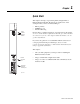
Chapter 1 Quick Start This chapter can help you get started quickly using the PLC-5 Ethernet Interface Module. We base the procedures here on the assumption that you have an understanding of: • • • Status indicator Transmit indicator PLC-5 products TCP/IP protocol Internet addressing Because this is a quick start guide for experienced users, this chapter does not contain detailed explanations about the procedures listed.
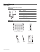
1-2 Quick Start Installing and Configuring the Interface Module Step 1 Check the contents of your shipment. Quantity: Step 2 Description: 1 PLC-5 Ethernet Interface Module (1785-ENET) 1 Connector kit containing 1 PLC-5 58-pin connector header 1 Industrial Automation Wiring and Grounding Guidelines, publication 1770-4.1 1 PLC-5 Ethernet Interface Module User Manual, publication 1785-6.5.19 Locate and have ready all equipment and tools necessary for installation.
Quick Start Step 3 Attach the connector header to the processor 1-3 See Chapter 2 Installing the Interface Module connector header Attach the interface module to this end. Push the exposed pins into the holes on the PLC-5 processor. ! Wear a grounding wrist strap to guard against ESD. 19379 Important: Make sure you carefully align the pins and holes before you press the connector header into the processor.
1-4 Quick Start Step 5 ! Install the interface module/processor combination in the left-most slot of the 1771 I/O chassis. See Chapter 2 Installing the Interface Module Be sure power to the 1771 I/O chassis is OFF. 20582±M Step 6 Assign an IP address to the interface module. See Chapter 3 Configuring the Interface Module for Ethernet Communication 1785-6.5.
Quick Start Step 7 Configure channel 3A for Ethernet communication. 1-5 See Chapter 3 Configuring the Interface Module for Ethernet Communication A. Be sure channel 3A is designated as the channel supporting the 1785-ENET module. • Your programming software must support configuration for channel 3A. • The PLC-5 processor must contain the proper firmware revision. See chapter 2.
1-6 Quick Start Step 8 Apply power to the I/O chassis and processor See Chapter 4 Communicating via the Interface Module Turn on the I/O chassis power supply. 20634±M Step 9 Establish an Ethernet connection. See Chapter 4 Communicating via the Interface Module Step 10 Check that the module is operating correctly. See Chapter 4 Communicating via the Interface Module Be sure that you assigned a diagnostics file to store status information for channel 3A. 1785-6.5.
Quick Start What You Have Done 1-7 You have now successfully installed and configured the PLC-5 Ethernet interface module for operation with the attached processor on an Ethernet link. If your module is operating successfully, it is not necessary to continue reading this manual. For more information about operation PLC-5 processors within your control system, see the Enhanced and Ethernet PLC-5 Programmable Controller User Manual, publication 1785-6.5.12.
1-8 Quick Start Notes: 1785-6.5.
Chapter 2 Installing the Interface Module Using This Chapter Read this chapter to: • • Status indicator Transmit indicator connect your Ethernet interface module to a PLC-5 processor install the processor and interface module combination in a 1771 I/O chassis.
2-2 Installing the Interface Module Use the interface module with a programming software package that supports configuration for channel 3A and the following processors: Series Revision Processor E and later any all Enhanced, Ethernet, and ControlNet PLC-5 processors D B PLC-5/11, -5/20, -5/26, -5/30, -5/40, -5/40L, -5/46, -5/60, -5/60L, -5/80, -5/86 PLC-5/20E, -5/40E, -5/80E PLC-5/20C, -5/40C, -5/80C C K PLC-5/11, -5/20, -5/26, -5/30, -5/40, -5/40L, -5/46, -5/60, -5/60L, -5/80, -5/86 PLC-5/20E
Installing the Interface Module 2-3 3. Locate and record the Ethernet hardware address. Allen-Bradley assigns each PLC-5 Ethernet interface module an Ethernet hardware address at the factory.
2-4 Installing the Interface Module Preventing Electrostatic Discharge (ESD) Damage The Ethernet interface module is shipped in a static-shielded container to guard against electrostatic discharge (ESD). ESD can damage integrated circuits or semiconductors in the module if you touch the backplane connector pins. Avoid electrostatic damage by observing the following precautions: • Remain in contact with an approved ground point while handling the module (by wearing a properly grounded wrist strap).
Installing the Interface Module Installing the Interface Module 2-5 To install the PLC-5 Ethernet Interface Module, you must: • attach the connector header to the processor • attach adhesive washers to the processor • connect the interface module to the processor • install the combination into the chassis ! ATTENTION: If your power supply is already installed in the chassis, be sure the chassis power supply is turned OFF before you begin the installation procedures.
2-6 Installing the Interface Module Important: Make sure you carefully align the pins and holes before you press the connector header into the processor. If you improperly align them, you will bend the connector header pins when you press them together. Do not use excessive force on the connector header when seating it into the processor. You do not need to key the connector.
Installing the Interface Module 2-7 1. Verify that power to the 1771 I/O chassis is OFF. 2. Raise the locking bar. ! Remember to wear a grounding wrist strap to guard against ESD. 3. Insert the module combination into the 1771 I/O chassis in the left-most slots and slide along the the card guides. 4. Lower the locking bar into place over the modules. 20615-M 1785-6.5.
2-8 Installing the Interface Module Removing the Interface Module To remove the interface module from its installed position, follow the instructions below. 1. Remove power to the 1771 I/O chassis. 2. Lift the locking bar up and away from the processor and interface module. Ejector tabs ! Remember to wear a grounding wrist strap to guard against ESD. 3. Lift the ejector tabs on the front of each module simultaneously and remove the connected modules. 4.
Chapter 3 Configuring the Interface Module for Ethernet Communication Using This Chapter Before You Begin For information about: See page: Before you begin 3-1 Configuring channel 3A 3-2 Specifying Ethernet-Specific information 3-2 Manually entering module configuration information 3-2 Using BOOTP to enter configuration information 3-4 Before configuring channel 3A for Ethernet communication, be sure to: • know the Ethernet hardware address (see page 2-2) • assign an IP address to the mod
3-2 Configuring the Interface Module for Ethernet Communication Configuring Channel 3A Once you know the unique IP address that you will assign to the PLC-5 Ethernet Interface Module, you must configure channel 3A so your network recognizes the module.
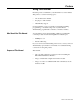
Configuring the Interface Module for Ethernet Communication 3-3 Enter configuration information in the appropriate fields. This field: Specifies: Configure by doing the following: Diagnostics file The file containing the channel’s status information Cursor to the field, type an unused integer file number (10-999), and press [Enter]. The system creates an integer file 44 words long.
3-4 Configuring the Interface Module for Ethernet Communication Using BOOTP to Enter Configuration Information Be sure you have assigned a diagnostics file in which to store channel status information. BOOTP is a protocol that supplies the interface module with configuration information at power-up. BOOTP lets you dynamically assign IP addresses to devices on the Ethernet link. To use BOOTP, a BOOTP server must exist on the local Ethernet subnet.
Configuring the Interface Module for Ethernet Communication 3-5 2. Make one copy of the Ethernet device template for every PLC-5 Ethernet Interface Module in your system (i.e. one line per module). 3. Edit each copy of the template as follows: The term “sidecar” in this template is a logical name used for identification in this file only. It is not associated with the stored processor name. A. Replace sidecar with the name you assigned the Ethernet interface module.
3-6 Configuring the Interface Module for Ethernet Communication Based on this configuration, the BOOTPTAB file would look like this: # # Legend: gw -- gateways ha -- hardware address # # # ht -- hardware type1 ip -- host IP address sm -- subnet mask # # vm -- BOOTP vendor extensions format2 tc -- template host #Default string for each type of Ethernet client defaults5E: ht=1:vm=rfc1048 #Entries device1: device2: device4: for 1785-ENET modules: tc=defaults5E:ip=12.34.56.
Chapter 4 Communicating via the Interface Module Using This Chapter Applying Power to the Chassis Monitoring the LEDs Once the PLC-5 Ethernet interface module is connected and configured, the interface module and the processor function as one unit.
4-2 Communicating via the Interface Module Monitor the series of blinks to determine the fault code. Count the first and last series of slow blinks, disregarding the series of fast blinks between the slow series.
Communicating via the Interface Module Establishing an Ethernet Connection 4-3 Fault Code Description 91 Sidecar module undefined message type. 92 Sidecar module requesting undefined pool. 93 Sidecar module illegal maximum pool size. 94 Sidecar module illegal ASCII message 95 Sidecar module reported fault, which may be the result of a bad program that corrupts memory or of a hardware failure. 96 Sidecar module not physically connected to the PLC-5 processor.
4-4 Communicating via the Interface Module Monitoring Ethernet Status Data Monitor the status of communication through the PLC-5 Ethernet interface module by accessing the Ethernet Channel 3A status screen. Be sure you have assigned a diagnostics file before you try to monitor channel 3A. See page 3-4. The diagnostic counter data displayed is stored in the diagnostics file you defined on the Ethernet Channel 3A configuration screen (see page 3-3). Status field: Commands Replies Ethernet 1785-6.5.
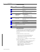
Communicating via the Interface Module Using the MSG Instruction MSG EN SEND/RECEIVE MESSAGE Control Block DN ER 4-5 The message (MSG) instruction transfers up to 1000 elements of data; the size of each element depends on the data table section that you specify and the type of message command that you use. One binary element contains one 16-bit word, for example, and one floating-point element contains two 16-bit words. The MSG instruction transfers data in packets.
4-6 Communicating via the Interface Module When you enter 3A as the port number, an Ethernet instruction entry screen appears. In addition to the information you entered previously this screen includes a field for entering the Host/Internet (IP) address. Enter the IP address of the destination processor here. This Parameter: Specifies: IP Address The MSG instruction’s destination node.
Communicating via the Interface Module 4-7 To communicate through a ControlLogix 1756-ENET module, you configure the multihop feature of a MSG instruction from the Ethernet PLC-5 processor (or PLC-5 processor with 1785-ENET sidecar module) to the target device. You need RSLogix 5 programing software. For more information, see the MSG instruction in the PLC-5 Programmable Controller Instruction Set Reference Manual, publication 1785-6.1.
4-8 Communicating via the Interface Module Code (Hexadecimal - Word 1 of the control block) 1785-6.5.19 November 1998 Description (Displayed on the data monitor screen) 00D5 Incorrect address for the local data table 0500 Message timed out waiting for a response from a client 1000 Illegal command specified in MSG instruction.
Communicating via the Interface Module Identifying the Interface Module within a Network 4-9 The PLC-5 Ethernet Interface Module supports the Simple Network Management Protocol (SNMP). The module responds automatically to SNMP requests and maintains a Management Information Base (MIB) file (Level II).
4-10 Communicating via the Interface Module Notes: 1785-6.5.
Appendix A Module Specifications PLC-5 Ethernet Interface Module (1785-ENET) Backplane Current 2.2A Heat Dissipation 37.54 BTU/hr Environmental Conditions Shock Operating Temperature 0 to 60° C (32–140° F) Storage Temperature –40 to 85° C (–40 to 185° F) Relative Humidity 5 to 95% (without condensation) Operating 30 g peak acceleration for 11±1 ms duration Non-operating 50 g peak acceleration for 11±1 ms duration Vibration (operating and non-operating) 2 g @ 10 to 500 Hz 0.
A-2 Module Specifications Notes: 1785-6.5.
Appendix B Performance Data PLC-5 Ethernet Interface Module (1785-ENET) The following tables show measured performance data for the 1785-ENET module. PLC-to-PLC (1 active MSG instruction) Operation: Words: MSG per second: ms per MSG: Words per second: read 1 20.2 49.5 20 read 20 19.8 50.5 396 read 100 18.8 53.2 1,880 read 1000 10.6 94.3 10,600 write 1 21.4 46.7 21 write 20 21.3 46.9 426 write 100 20.4 49.0 2,040 write 1000 11.4 87.
B-2 Performance Data Workstation-to-PLC (Solicited Synchronous) Operation: Words: MSG per second: ms per MSG: Words per second: read 1 45.8 21.8 45 read 20 43.6 22.9 872 read 100 41.8 23.9 4,180 read 1000 23.3 42.9 23,300 write 1 45.4 22.0 45 write 20 44.3 22.6 886 write 100 41.7 24.0 4,170 write 1000 21.9 45.7 21,900 1785-6.5.
Appendix C SNMP Management Information Base (MIB) II Data Groups Simple Network Management Protocol (SNMP) specifies the diagnostic data that a host computer must maintain for a network management software to access. Hosts typically keep statistics on the status of their network interfaces, incoming and outgoing traffic, dropped datagrams, and error messages generated. Network management protocols let network management software access these statistics.
C-2 SNMP Management Information Base (MIB) II Data Groups Group: MIB: Description: Interfaces (continued) ifOutOctets total octets sent on the media ifOutOcastPkts unicast packets from above ifOutNUcastPkts broadcast/multicast packets from above ifOutDiscards packets discarded due to resource limitations ifOutErrors packets discarded due to errors ifOutQlen packet size of output queue ifSpecific MIB-specific pointer udplndataGrams datagrams delivered above udpNoPorts datagrams destined
SNMP Management Information Base (MIB) II Data Groups C-3 Group: MIB: Description: IP (continued) ipRouteProto mechanism used to determine route ipRouteAge age of route in seconds ipRouteMask subnet mask for route ipNetToMediaflIndex interface number ipNetToMediaPhysAddress media address of mapping ipNetToMediaNetAddress IP address of mapping ipNetToMediaType how mapping was detemined ipReasmReqds fragments received needing reassembly ipReasmOKs datagrams successfully reassembled ipR
C-4 SNMP Management Information Base (MIB) II Data Groups 1785-6.5.
Appendix D Status LED Error Codes Interpreting LED Error Codes When the status LED blinks red, it signals that a hardware or software fault has been detected and it reports that error via a code. This code is a two-digit fault code signalled by a flash sequence. First, the LED begins the sequence with ten rapid flashes. Then the LED signals the first digit of the code by a number of slow flashes. Approximately two seconds after the LED displays the first digit, the LED displays the second digit.
D-2 Status LED Error Codes 1785-6.5.
Allen-Bradley Publication Problem Report If you find a problem with our documentation, please complete and return this form Pub. Name PLC-5 Enthernet Interface Module User Manual Cat. No. 1785-ENET Check Problem(s) Type: Pub. No. 1785-6.5.19 Pub. Date November 1998 Part No.
PLEASE FASTEN HERE (DO NOT STAPLE) PLEASE FOLD HERE NO POSTAGE NECESSARY IF MAILED IN THE UNITED STATES BUSINESS REPLY MAIL FIRST-CLASS MAIL PERMIT NO.
ControlLogix, ControlBus, Logix5550, PLC-5, PLC-3, PLC-2, SLC, ControlNet, DH+, Allen-Bradley, and Rockwell Software are trademarks of Rockwell Automation. DeviceNet is a trademark of the Open DeviceNet Vendor Association. Ethernet is a trademark of Digital Equipment Corporation, Intel, and Xerox Corporation. 1785-6.5.
Allen-Bradley, a Rockwell Automation Business, has been helping its customers improve productivity and quality for more than 90 years. We design, manufacture and support a broad range of automation products worldwide. They include logic processors, power and motion control devices, operator interfaces, sensors and a variety of software. Rockwell is one of the world’s leading technology Worldwide representation.