
User manual


Instruction Set
Processor and Message 3-41
Processor Control and Message Instructions
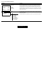
Instruction Description
Proportional, Integral,
and Derivative
PID
Status Bits:
EN - Enable
DN - Done Bit
If the input conditions go false-to-true, the processor performs PID calculations and calculates a
new control output (for Classic PLC-5 processors). The control block (N10:0) contains the
instruction information for the PID. The PID gets the process variable from N15:13 and sends
the PID output to N20:21. The tieback stored in N15:14 handles the manual control station.
For Enhanced, Ethernet, and ControlNet PLC-5 processors, you can use the PD control block. (If
you use PD control block, then there is no done bit.) Also, the rung input conditions only need to
be true for these processors.
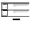
Message
MSG
If the input conditions are true, the data is transferred according to the instruction parameters
you set when you entered the message instruction. The Control Block (N7:10) contains status
and instruction parameters.
For Enhanced, Ethernet, and ControlNet PLC-5 processors, you can use the MG control block.
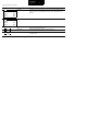
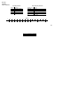
PID
Control Block N10:0
Proc Variable N15:13
Tieback N15:14
Control Output N20:21
PID
SEND/RECEIVE MSG
Control Block N7:10
MSG
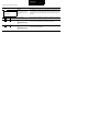
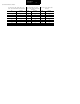
Bit # Status Bits
15 EN - Enable
14 ST - Start Bit
13 DN - Done Bit
12 ER - Error Bit
11 CO - Continuous
10 EW - Enabled-Waiting
9NR - No Response
8 TO - Time Out Bit