
User manual


Addressing
Module Placement 2-8
I/O Addressing Modes
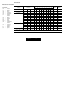
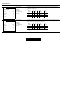
Discrete I/O Module Placement for Addressing Modes
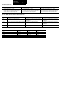
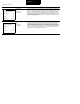
Addressing Concept Summary
2-slot addressing 1-slot addressing 1/2-slot addressing
• two I/O module slots = 1 group
• each physical 2-slot I/O group corresponds to one
word (16 bits) in the input image table and one
word (16 bits) in the output image table
• one I/O module slot = 1 group
• each physical slot in the chassis corresponds to
one word (16 bits) in the input image table and one
word (16 bits) in the output image table
• one half of an I/O module slot = 1 group
• each physical slot in the chassis corresponds to
two words (32 bits) in the input image table and
two words (32 bits) in the output image table
I/O 2-slot addressing 1-slot addressing 1/2-slot addressing
8-pt
modules
no restriction on module placement no restriction on module placement, but does
not make best use of I/O image and available
I/O addresses
no restriction on module placement, but does
not make best use of I/O image and available
I/O addresses
16-pt
modules
must use 1 input and 1 output module per even/odd
slot pair
no restriction on module placement no restriction on module placement, but does
not make best use of I/O image and available
I/O addresses
32-pt
modules
not allowed must use 1 input and 1 output module per
even/odd slot pair
no restriction on module placement
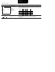
If you are using this chassis size: 2-slot addressing 1-slot addressing 1/2-slot addressing
4-slot 1/4 rack 1/2 rack 1 rack
8-slot 1/2 rack 1 rack 2 racks
12-slot 3/4 rack 1 1/2 racks 3 racks
16-slot 1 rack 2 racks 4 racks