785 PLC-5 Programmable Controllers Quick Reference Front Panels ........................ 1-1 Processor Comparison ......... 1-6 1771 I/O Chassis ............... 1-10 Power Supplies.................. 1-11 Keyswitch.......................... 1-13 Processor Status File ......... 1-14 I/O Status File .................... 1-30 Data Table Files ...................2-1 Program Files ......................2-4 I/O Image Addressing ...........2-5 Logical Addressing...............2-6 Indexed Addressing..............
Using this Manual This Quick Reference provides information frequently needed for using and maintaining your Allen-Bradley PLC-5 processor. It is intended for reference purposes only, and not as the sole source of information. For more specific information on any topic in this Quick Reference, see: • Enhanced and Ethernet PLC-5 Family Programmable Controllers User Manual, publication 1785-6.5.12 • Classic PLC-5 User Manual, publication 1785-6.2.1 • ControlNet PLC-5 Programmable Controllers Phase 1.
The Safety Guidelines for the Application, Installation, and Maintenance of Solid State Control, publication SGI-1.1 (available from your local Allen-Bradley office), describes some important differences between solid-state equipment and electromechanical devices which should be taken into consideration when applying products such as those described in this publication.
Conventions The table below describes the naming conventions used in this manual: This name: Represents these processors: Enhanced PLC-5/11™PLC-5/40™ PLC-5/20™PLC-5/60™ PLC-5/30™PLC5/80™ PLC-5/40L™PLC-5/60L™ Ethernet PLC-5/20E™PLC-5/40E™ PLC5/80E™ ControlNet Phase 1.5 PLC-5/20C15™ 5/40C15™ 5/80C15™ Classic PLC-5/10™PLC-5/15™ PLC-5/12™PLC-5/25™ ☞ You see this symbol in the lower right-hand corner of the page when information is continued on the next page.
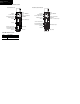
Front Panel – Enhanced PLC-5 Processors PLC-5/11 Processor PLC-5/20 Processor Indicators: Battery (red) Processor RUN/FAULT (green/red) Force (amber) Channel 0 communication status (green) Keyswitch Install memory module here Channel 0 - on-board serial port Channel 1A status indicator (green/red) Connect programming terminal here when channel 1A is configured for DH+ communications Channel 1A communication port Hardware Components Front Panel 1-1 Battery holder Channel 1B status indicator (green/red)
Hardware Components Front Panel 1-2 PLC-5/30, -5/40, -5/60, -5/80 Processor Keyswitch PLC-5/40L, -5/60L Processor Channel 2B status indicator (green/red) Channel 2A status indicator (green/red) Channel 2 status indicator (green/red) Connect programming terminal here when channel 2A is configured for DH+ communications Channel 2 extended-local I/O communication port Channel 2A communication port Channel 2B communication port Indicators: Battery (red) Processor RUN/FAULT (green/red) Force (amber) Co
Front Panel – Ethernet PLC-5 Processors PLC-5/40E, -5/80E Processor PLC-5/20E Processor Indicators: Keyswitch Channel 2 Ethernet status indicators Channel 2 Battery (red) Processor RUN/FAULT (green/red) Force (amber) Channel 0 communication status (green) Connect programming terminal here Channel 1A Keyswitch Channel 2 Ethernet status indicators Channel 2 Install memory module here Channel 0 - on-board serial port Channel 1A status indicator (green/red) Indicators: Channel 1B status indicator (gr
Hardware Components Front Panel 1-4 Front Panel – ControlNet PLC-5 Processors PLC-5/20C15 Processor PLC-5/40C15, -5/80C15 Processor Battery Keyswitch I/O Status Indicator Channel 2 Status Indicators Network Access Port Processor RUN/FAULT Force Channel 0 Communication ACTIVE/FAULT Battery Keyswitch I/O Status Indicator Channel 2 Status Indicators Network Access Port Channel 2 Channel 2 Processor RUN/FAULT Force Channel 0 Communication ACTIVE/FAULT Channel 0 - on-board serial port Memory Module Spac
Hardware Components Front Panel – Classic PLC-5 Processors PLC-5/10 Processor DH+ communication indicator ACTIVE/FAULT (green/red) PLC-5/12, -5/15, -5/25 Processor Indicators: REM I/O indicator ACTIVE/FAULT (green/red) Keyswitch Battery (red) Processor RUN/FAULT (green/red) Force (amber) PR O G Adapter indicator (green) Battery holder Write the DH+ network station number on this label Connect programming terminal here Connect DH+ link here Connect remote I/O link here 12373 Hardware Components Fro
Hardware Components Processor Comparison 1-6 Comparison Chart for PLC-5 Family Processors Processor Memory (Words) Local Chassis Remote Chassis (I/O Racks) I/O Capacity Communication PLC-5/10 6K 1 resident none 128 (8-pt) 1, 256 (16-pt) 1, 512 (32-pt) 1 DH+ link PLC-5/12 6K 1 resident none 128 (8-pt) 1, 256 (16-pt) 1, 512 (32-pt) 1 adapter, DH+ link PLC-5/15 6K 1 resident (expands to 14K) 12 (3 I/O racks) • 512 1 • 512 inputs and 512 outputs using 16- or 32-pt modules 2 adapter/remot
PLC-5 comparison chart continued...
Hardware Components Processor Comparison 1-8 PLC-5 comparison chart continued...
PLC-5 comparison chart continued... Processor Memory (Words) Local Chassis PLC-5/60L 3 64K PLC-5/80 3.
Hardware Components 1771 I/O Chassis 1-10 1771 I/O Chassis for PLC-5 Family Processors Catalog Number Chassis Size 1771-A1B 1771-A2B 1771-A3B 1771-A3B1 1771-A4B 4-slot 8-slot 12-slot 12-slot 16-slot Mounting Backpanel 19” Rack X X X X X Power Supply Socket X left left top left left 7KH 3/& SURFHVVRUV DUH DOVR FRPSDWLEOH ZLWK $ $ DQG $ FKDVVLV ZLWK VORW SRZHU VXSSOLHV RQO\ When using these processors with the 1771-A1, A2, and A4 chassis: Only this mode of addressing is supported: Cla
Power Supply Modules in a Chassis (containing a PLC-5 processor) Output Current (in amps) when Parallel with: Input Power (in Amps) P3 P4 P4S 1771-P3 120V ac 3 6 11 11 slot 1771-P4 120V ac 8 11 16 16 slot 1771-P4S 120V ac 8 11 16 16 1771-P4S1 100V ac 8 1771-P4R 120V ac 8, 16, 24 2 1771-P5 24V dc 8 1771-P6S 220V ac 8 1771-P6S1 200V ac 8 1771-P6R 220V ac 8, 16, 24 2 slot 1771-P7 120/220V ac 16 external 1 1771-PS7 120/220V ac 16 external 1 2 P4S1 P5 P6S
Hardware Components Power Supplies 1-12 Power Supplies in a Remote Chassis (1771-ASB) or an Extended Local I/O Chassis (1771-ALX) Output Current Output Current (in amps) when Parallel with: (in Amps) P3 P4 P4S 3 6 11 11 slot 120V ac 8 11 16 16 slot 120V ac 8 11 16 16 1771-P4S1 100V ac 8 1771-P4R 120V ac 8, 16, 24 2 1771-P5 24V dc 8 1771-P6S 220V ac 8 1771-P6S1 200V ac 8 1771-P6R 220V ac 8, 16, 24 2 1771-P1 120/220V ac 6.5 external 1 1771-P2 120/220V ac 6.
Front Panel Keyswitch Keyswitch Position Operation Execute programs (with outputs enabled) Execute programs (with outputs disabled) Save program to disk Restore programs Create or delete: ladder files, SFC files, data table files Edit online: ladder files and SFC files (program files already exist) Force live outputs Prohibit processor from scanning program Change operating mode using a programming device Download to/from EEPROM Automatically configure remote I/O Edit data table values (data table files alr
Hardware Components Processor Status File 1-14 Processor Status File This word of the status file: Stores: S:0 Arithmetic flags • bit 0 = carry • bit 1 = overflow • bit 2 = zero • bit 3 = sign Processor status and flags Bit Description 0 RAM checksum is invalid at power-up 1 processor in RUN mode 2 processor in TEST mode 3 processor in PROG mode 4 processor burning EEPROM 5 processor in download mode 6 processor has test edits enabled 7 mode select switch in REMOTE position 8 forces enabled 9 forces pr
processor status file continued This word of the status file: Stores: S:7 Global status bits: • S:7/0-7 - - rack fault bits for racks 0-7 • S:7/8-15 - - rack queue-full bits for racks 0-7 See also S:27, S:32, S:33, S:34, and S:35 Last program scan (in ms) Maximum program scan (in ms) Switch setting information • bits 0 - 6 DH+ station number • bit 11-12 are set based on the I/O chassis backplane switches • bit 12 bit 11 = I/O chassis addressing 0 0 illegal 1 0 1/2-slot 0 1 1-slot 1 1 2-slot • bit 1
Hardware Components Processor Status File 1-16 processor status file continued...
processor status file continued...
Hardware Components Processor Status File 1-18 processor status file continued...
processor status file continued... This word of the status file: Stores: S:12 continued...
Hardware Components Processor Status File 1-20 processor status file continued... This word of the status file: Stores: S:12 continued...
processor status file continued... This word of the status file: Stores: S:12 continued...
Hardware Components Processor Status File 1-22 processor status file continued... This word of the status file: Stores: S:12 continued...
processor status file continued...
Hardware Components Processor Status File 1-24 processor status file continued... This word of the status file: Stores: S:24 S:25 S:261. Indexed addressing offset Reserved User control bits Bit Description 0 Restart/continuous SFC: when reset, processor restarts at first step in SFC. When set, processor continues with active step after power loss or change to RUN 1 Start-up protection after power loss: when reset, no protection.
processor status file continued... This word of the status file: Stores: S:29 S:30 S:31 S:32 Fault routine file STI setpoint STI file number Global status bits: • S:32/0-7 - - rack fault bits for racks 10-17 (octal) • S:32/8-15 - - rack queue-full bits for racks 10-17 See also S:7, S:27, S:33, S:34, and S:35. Rack control bits: • S:33/0-7 - - I/O rack inhibit bits for racks 10-17 (octal) • S:33/8-15 - - I/O rack reset bits for racks 10-17 See also S:7, S:27, S:32, S:34, and S:35.
Hardware Components Processor Status File 1-26 processor status file continued... This word of the status file: Stores: Classic PLC-5 processors use only 37 words for the status file. Therefore, the following descriptions apply only to Enhanced, Ethernet, and ControlNet processors.
processor status file continued... This word of the status file: S:60 S:61 S:62 S:63 S:64 S:65 S:66 S:72* S:73* S:74* S:75* S:76 S:77 S:78 Stores: Extended-local I/O channel discrete maximum scan (in ms) Extended-local I/O channel block-transfer scan (in ms) Extended-I/O channel maximum block-transfer scan (in ms) Protected processor data table protection file number The number of remote block transfer command blocks being used by channel pair 1A/1B.
Hardware Components Processor Status File 1-28 processor status file continued... This word of the status file: Stores: S:79 MCP inhibit bits Bit 0 for MCP A Bit 1 for MCP B etc. MCP file number MCP scan time (in ms) MCP max scan time (in ms) The above sequence applies to each MCP; therefore, each MCP has 3 status words. For example, word 80: file number for MCP A word 81: scan time for MCP A word 82: maximum scan time for MCP A word 83: file number for MCP B word 84: scan time for MCP B etc.
I/O Status File Format (N:15 is defined in word S:16 of the processor status file.
Hardware Components I/O Status File 1-30 Word 1 in the I/O Status File N15:14 15 Present Bits 14 13 12 11 10 09 Fault Bits 08 07 Not Used 06 05 Not Used This bit: Fault bits Present bits Corresponds to: 00 first 1/4 rack starting I/O group 0 01 second 1/4 rack starting I/O group 2 02 third 1/4 rack starting I/O group 4 03 fourth1/4 rack starting I/O group 6 08 first 1/4 rack starting I/O group 0 09 second 1/4 rack starting I/O group 2 10 third 1/4 rack starting I/O group 4 11
Word 2 in the I/O Status File N15:15 15 Reset Bits 14 13 12 11 10 09 Inhibit Bits 08 Not Used Inhibit bits Reset bits Hardware Components I/O Status File 1-31 06 05 04 03 02 01 00 Not Used This bit: 07 Corresponds to: 00 01 02 03 08 09 10 11 first 1/4 rack starting I/O group 0 second 1/4 rack starting I/O group 2 third 1/4 rack starting I/O group 4 fourth1/4 rack starting I/O group 6 first 1/4 rack starting I/O group 0 second 1/4 rack starting I/O group 2 third 1/4 rack starting
Addressing Data Table Files (Enhanced, Ethernet, and ControlNet Processors) Series E and Later – File Type Output image Input image Status Bit (binary) Timer Counter Control Integer Floating-point ASCII BCD Block-transfer CIO Message PID SFC status ASCII string Unused File-Type Identifier File Number O I S B T C R N F A D BT CT MG PD SC ST -- 0 1 2 3a 4a 5a 6a 7a 8a 3-999 3-999 3-999 3-999 3-999 3-999 3-999 3-999 9-999 Maximum Size of File 16-bit words and structuresc PLC-5/11, -5/20 PLC-5/30 32 32 1
Addressing Data Table Files File-Type Identifier File Number Output image Input image Status Bit (binary) O I S B 0 1 2 3a Timer T 41 Counter C 51 Control R 61 Integer N 7 1 Floating-point F ASCII BCD Block-transfer Message A D BT MG 81 3-999 3-999 3-999 3-999 PID PD 3-999 SFC status ASCII string SC ST 3-999 3-999 Unused -- 9-999 File Type 2-2 Maximum Size of File 16-bit words and structures PLC-5/11, -5/20 PLC-5/30 32 32 128 64 64 128 PLC-5/40 128 128 128 1000 words
Data Table Files - Classic Processors Number (Default File) File Description PLC-5 Memory Data Table program Maximum Size of File (16-bit words and structures) PLC-5/10, -5/12, -5/15 PLC-5/25 Memory Used Output Image O 0 32 64 2/file + 1/word Input Image I 1 32 64 2/file + 1/word Status S 2 32 32 2/file + 1/word Bit (binary) B 3-999 (3) 1000 words 2/file + 1/word Timer T 3-999 (4) 3000 words/1000 structures 2/file + 3/structure Counter C 3-999 (5) 3000 words/1000 struct
Addressing Program Files 2-4 Program Files PLC-5 Memory Data Table program Program File Number Program File Number Description Classic PLC-5 Processors Enhanced, Ethernet, and ControlNet PLC-5 Processors System 0 0 Sequential Function 1 1 - 1999 2 Ladder 2 - 999 2 - 1999 2 Structured Text1 2 - 1999 2 Assigned as needed: 3 - 999 2 - 1999 Subroutines Fault Routines Selectable Timed Interrupts Processor Input Interrupts 1 SFC Step/Transition SFC Actions 1 1 2 Enhanced, Ethernet, and Co
I/O Image Addressing a I/O data type identifier I - input device a:bbc/dd O - output device bb I/O rack number 00 - 03 (octal) PLC-5/10, -5/11, -5/12, -5/15, -5/20, -5/20E, -5/20C15 00 - 07 (octal) PLC-5/25, -5/30 00 - 17 (octal) PLC-5/40, -5/40L, -5/40E, -5/40C15 00 - 27 (octal) PLC-5/60, -5/60L, -5/80, -5/80E, -5/80C15 c I/O group number 0 - 7 (octal) dd terminal (bit) number 00 - 17 (octal) Examples: I:001/07 O:074/10 Addressing I/O Images/Symbolic 2-5 input device, rack 00, group 1,
Addressing Logical 2-6 Logical Addressing # X F: 3. s / b file address identifier Where: Is the: # File address identifier.
Indexed Addressing Indexed addressing offsets an address by the number of elements you select. You store the offset value in an offset word in word 24 of the status file S:24. The processor starts operation at the base address plus the offset. You can manipulate the offset word in your ladder logic. The indexed address symbol is the # character. Place the # character immediately before the file-type identifier in a logical a ddress. Important: File instructions manipulate the offset value stored at S:24.
Addressing Module Placement 2-8 I/O Addressing Modes 2-slot addressing 1-slot addressing 1/2-slot addressing • two I/O module slots = 1 group • one I/O module slot = 1 group • one half of an I/O module slot = 1 group • each physical 2-slot I/O group corresponds to one • each physical slot in the chassis corresponds to • each physical slot in the chassis corresponds to word (16 bits) in the input image table and one one word (16 bits) in the input image table and one two words (32 bits) in the input ima
Instruction Set Instruction Set – Status Bits Category Status Bits: .EN – enable .TT – timing .DN – done .OV – overflow .UN – underflow .EU – unload enable .FD – found .UL – unload .ER – error .EM – empty .CD – count down enable .CU – count up enable .IN – inhibit .EU – queue Word 0 Mnemonic TIMER (T4:n) 2 TON TOF COUNTER (C5:n) 2 CTU CTD FILE (R6:n) 2 FAL 15 RTO COMPUTE (R6:n) 2 DN DN 11 DN DN .
Instruction Set Relay 3-2 Relay Instructions Instruction Description I:012 ] [ 07 Examine On XIC Examine data table bit I:012/07, which corresponds to terminal 7 of an input module in I/O rack 1, I/O group 2. If this data table bit is set (1), the instruction is true. I:012 ]/[ 07 Examine Off XIO Examine data table bit I:012/07, which corresponds to terminal 7 of an input module in I/O rack 1, I/O group 2. If this data table bit is reset (0), the instruction is true.
relay instructions continued... Instruction Description 01 (IIN) Immediate Input IIN 01 (IOT) Immediate Output IOT This instruction updates a word of input–image bits before the next normal input-image update. For a local chassis, program scan is interrupted while the inputs of the addressed I/O group are scanned; for a remote or ControlNet chassis, program scan is interrupted only to update the input image with the latest states as found in the remote I/O or ControlNet buffer.
Instruction Set Relay 3-4 relay instructions continued... Instruction Description IDI IMMEDIATE DATA INPUT Data file offset Immediate Data Output IDO for ControlNet processors only If the input conditions are true, an immediate data output is initiated that updates the private ControlNet output buffers from the source file before the next normal output-image update. The Data file offset (175) is the offset into the buffer where the data is stored.
Timer Instructions Instruction Description Timer On Delay TON TON TIMER ON DELAY Timer T4:1 Status Bits: EN – Enable TT – Timer Timing DN – Done If the input conditions go true, timer T4:1 starts incrementing in 1-second intervals. When the accumulated value is greater than or equal to the preset value (15), the timer stops and sets the timer done bit. Rung Condition EN 15 TT 14 DN 13 ACC Value TON Status Time Base 1.
Instruction Set Timer 3-6 timer instructions continued... Instruction Description Retentive Timer On RTO RTO RETENTIVE TIMER ON Timer T4:10 Time Base 1.0 Preset 10 Accum Status Bits: EN - Enable TT - Timer Timing DN - Done 0 T4:1 (RES) Timer Reset RES If the input conditions go true, timer T4:10 starts incrementing in 1-second intervals as long as the rung remains true. When the rung goes false, the timer stops. If the rung goes true again, the timer continues.
Counter Instructions Instruction Description Count Up CTU CTU COUNT UP Counter C5:1 Preset 10 Accum 0 Status Bits: CU-Count Up CD-Count Down DN-Count Done OV-Overflow UN-Underflow If the input conditions go true, counter C5:1 starts counting, incrementing by 1 every time the rung goes from false-to-true. When the accumulated value is greater than or equal to the preset value (10), the counter sets the counter done bit.
Instruction Set Counter 3-8 counter instructions continued... Instruction Description Count Down CTD CTD COUNT DOWN Counter C5:1 Preset 10 Accum 35 C5:1 (RES) Status Bits: CU-Count Up CD-Count Down DN-Count Done OV-Overflow UN-Underflow Counter Reset RES If the input conditions go true, counter C5:1 starts counting, decrementing by 1 every time the rung goes from false-to-true. When the accumulated value is less than or equal to the preset value (10), the counter resets the counter done bit.
Compare Instructions Instruction Description CMP Compare CMP If the expression is true, this input instruction is true. The CMP instruction can perform these operations: equal (=), less than (<), less than or equal (<=), greater than (>), greater than or equal (>=), not equal (<>). Complex expressions (up to 80 characters) are valid with Enhanced and ControlNet PLC–5 processors only.
Instruction Set Compare 3-10 compare instructions continued... Instruction Description Mask Compare Equal MEQ MEQ MASKED EQUAL Source Mask Compare The processor takes the value in the Source (D9:5) and passes that value through the Mask (D9:6). Then the processor compares the result to the Compare value (D9:10). If the result and this comparison values are equal, the instruction is true.
compare instructions continued... Instruction Description xxx xxxxxxxxxxxxx Source A N7:5 3 Source B N7:10 1 Source A Source B EQU GEQ GRT LEQ LES 10 10 T T F T F NEQ F 5 6 F F F T T T 21 20 F T T F F T –30 –31 F T T F F T –15 –14 F F F T T T Equal to EQU Greater than or Equal GEQ Greater than GRT Less than or Equal LEQ Less than LES Not Equal NEQ If the value in Source A (N7:5) is = to the value in Source B (N7:10), this instruction is true.
Instruction Set Compute 3-12 Compute Instructions Instruction Description CPT Compute CPT If the input conditions go true, evaluate the Expression N7:4 – (N7:6 * N7:10) and store the result in the Destination (N7:3). The CPT instruction can perform these operations: add (+), subtract (–), multiply (*), divide (|), convert from BCD (FRD), convert to BCD (TOD), square root (SQR), logical and (AND), logical or (OR), logical not (NOT), exclusive or (XOR), negate (–), clear (0), and move.
compute instructions continued... Instruction Description Addition ADD ADD ADD Status Bit Source A N7:3 3 Source B N7:4 1 Dest ARCSINE Destination C N7:12 4 ASN Source When the input conditions are true, add the value in Source A (N7:3) to the value in Source B (N7:4) and store the result in the Destination (N7:12). F8:17 0.
Instruction Set Compute 3-14 compute instructions continued... Instruction Description ATN ARCTANGENT Source F8:21 0.7853982 Destination F8:22 0.
compute instructions continued... Instruction Description Clear CLR CLR When the input conditions are true, clear BCD file 9, word 34 (set to zero). CLR Status Bit Description Dest C always reset V always reset Z always set S always reset D9:34 0000 COS COSINE Source F8:13 0.7853982 Destination F8:14 0.
Instruction Set Compute 3-16 compute instructions continued... Instruction Description Division DIV DIV DIVIDE Status Bit Source A N7:3 3 Source B N7:4 1 Dest N7:12 3 LN NATURAL LOG Source Destination When the input conditions are true, divide the value in Source A (N7:3) by the value in Source B (N7:4) and store the result in the Destination (N7:12). N7:0 5 F8:20 1.
compute instructions continued... Instruction Description LOG LOG BASE 10 Source Destination N7:2 5 When the input conditions are true, take the log base 10 of the Source (N7:2) and store the result in the Destination (F8:3). The Source must be positive (greater than 0). Status Bit C F8:3 0.
Instruction Set Compute 3-18 compute instructions continued... Instruction Description Negate NEG NEG NEGATE Source Destination When the input conditions are true, take the opposite sign of the Source (N7:3) and store the result in the Destination (N7:12). This instruction turns positive values into negative values and negative values into positive values.
compute instructions continued... Instruction Description Square Root SQR SQR SQUARE ROOT Source Destination Status Bit N7:3 25 N7:12 5 SRT SORT File When the input conditions are true, take the square root of the Source (N7:3) and store the result in the Destination (N7:12).
Instruction Set Compute 3-20 compute instructions continued... Instruction Description STD STANDARD DEVIATION File Dest #N7:1 N7:0 Control R6:0 Length 4 Position Status Bits: EN - Enable DN - Done Bit ER - Error Bit 0 Subtract SUB SUB SUBTRACT When the input conditions go from false-to-true, the elements in N7:1, N7:2, N7:3 and N7:4 are used to calculate the standard deviation of the values and store the result in the Destination (N7:0). The result is stored in N7:0.
compute instructions continued... Instruction Description TAN TANGENT Source Destination F8:15 0.7853982 Tangent TAN (Enhanced, Ethernet and ControlNet PLC-5 processors only) When the input conditions are true, take the tangent of the Source (F8:15) and store the result in the Destination (F8:16). The Source must be greater than or equal to –102943.7 and less than or equal to 102943.7. The Source is interpreted as radians. Status Bit C F8:16 1.
Instruction Set Logical 3-22 Logical Instructions Instruction Description AND AND BITWISE AND Source A D9:3 3F37 Source B D9:4 00FF Dest D9:5 0037 Source A 0 1 0 1 NOT Operation NOT NOT Source A D9:3 00FF Destination D9:5 FF00 Status Bit C When the input conditions are true, the processor evaluates an AND operation (bit-by-bit) between Source A (D9:3) and Source B (D9:4) and stores the result in the Destination (D9:5).
logical instructions continued... Instruction Description OR OR BITWISE INCLUS OR Source A D9:3 3F37 Source B D9:4 00FF Dest D9:5 3FFF BITWISE EXCLUS OR Source A D9:3 3F37 Source B D9:4 3F37 Dest D9:5 0000 Status Bit C V Z S Source A 0 1 0 1 Exclusive OR XOR XOR When the input conditions are true, the processor evaluates an OR operation (bit-by-bit) between Source A (D9:3) and Source B (D9:4) and stores the result in the Destination (D9:5).
Instruction Set Conversion 3-24 Conversion Instructions Instruction Description Convert from BCD FRD FRD FROM BCD Source Destination When the input conditions are true, convert the value in the Source (D9:3) to an integer value and store the result in the Destination (N7:12). The source must be in the range of 0-9999 (BCD).
conversion instructions continued... Instruction Description Convert to Degrees DEG DEG RADIANS TO DEGREE Source F8:7 0.
Instruction Set Bit Modify and Move 3-26 Bit Modify and Move Instructions Instruction Description BTD Bit Distribute BTD When the input conditions are true, the processor copies the number of bits specified by Length, starting with the Source bit (3) of the Source (N7:3), and placing the values in the Destination (N7:4), starting with the Destination bit (10). Move MOV When the input conditions are true, move a copy of the value in Source (N7:3) to the Destination (N7:12).
bit modify and move instructions continued... Instruction Description Masked Move MVM MVM MASKED MOVE Source Mask Dest bit Length D9:3 478F When the input conditions are true, the processor passes the value in the Source (D9:3) through the Mask (D9:5) and stores the result in the Destination (D9:12). This overwrites the original value in the Destination.
Instruction Set File Instructions 3-28 File Instructions Instruction Description File Arithmetic and Logic FAL FAL FILE ARITH/LOGICAL Control Length Position Mode Dest Expression R6:1 8 0 ALL #N15:10 #N14:0 – 256 File Fill FLL FLL FILL FILE Source Destination Length Status Bits: EN – Enable DN – Done Bit ER – Error Bit N10:6 #N12:0 5 When the input conditions go from false-to-true, the processor reads 8 elements of N14:0, and subtracts 256 (a constant) from each element.
file instructions continued... Instruction Description File Search and Compare FSC FSC FILE SEARCH/COMPARE Control Length Position Mode Expression R9:0 90 0 10 #B4:0 <>#B5:0 File Copy COP COP COPY FILE Source Destination Length Status Bits: EN - Enable DN - Done Bit ER - Error Bit IN - Inhibit Bit FD - Found Bit When the input conditions go from false-to-true, the processor performs the not-equal-to comparison on 10 elements per scan for 9 scans (numeric mode) between files B4:0 and B5:0.
Instruction Set Diagnostic 3-30 Diagnostic Instructions Instruction Description File Bit Compare FBC FBC FILE BIT COMPARE Source Reference Result Cmp Control Length Position Result Control Length Position #I:031 #B3:1 #N7:0 R6:4 48 0 R6:5 10 0 Status Bits: EN - Enable DN - Done Bit ER - Error Bit IN - Inhibit Bit FD - Found Bit When the input conditions go from false-to-true, the processor compares the number of bits specified in the Cmp Control Length (48) of the Source file (#I:031) with the bits i
diagnostic instructions continued...
Instruction Set Shift Register 3-32 Shift Register Instructions Instruction Description Bit Shift Left BSL BSL BIT SHIFT LEFT File Control Bit Address Length #B3:1 R6:53 I:022/12 5 Bit Shift Right BSR BSR BIT SHIFT RIGHT File #B3:2 Control R6:54 Bit Address Length Status Bits: EN - Enable DN - Done Bit ER - Error Bit UL - Unload Bit If the input conditions go from false-to-true, the BSL instruction shifts the number of bits specified by Length (5) in File (B3), starting at bit 16 (B3:1/0 = B3/1
shift register instructions continued...
Instruction Set Shift Register 3-34 shift register instructions continued... Instruction Description LFL LIFO LOAD Source LIFO N70:1 #N70:3 Control R6:61 Length 64 Position 0 LFU LIFO UNLOAD LIFO #N70:3 Dest N70:2 Control R6:61 Length 64 Position 0 LIFO Load LFL (Enhanced, Ethernet, and ControlNet PLC-5 processors only) When the input conditions go from false-to-true, the processor loads N70:1 into the next available element in the LIFO file #N70:3, as pointed to by R6:61.
Sequencer Instructions Instruction SQI SEQUENCER INPUT File Mask Source Control Length Position SQL SEQUENCER LOAD File Source Control Length Position SQO SEQUENCER OUTPUT File Mask Dest Control Length Position Description Sequencer Input SQI The SQI instruction compares the Source (#I:031) input image data through a Mask (FFF0) to Reference data (#N7:11) to see if the two files are equal. The operation is controlled by the information in the control file R6:21.
Instruction Set Program Control 3-36 Program Control Instructions Instruction Description (MCR) Master Control Reset MCR If the input conditions are true, the program scans the rungs between MCR instruction rungs and processes the outputs normally. If the input conditions are false, all non-retentive outputs between the MCR-instruction rungs are reset. 10 (JMP) Jump JMP If the input conditions are true, the processor skips rungs by jumping to the rung identified by the label (10).
program control instructions continued... Instruction Description NXT Next NXT The NXT instruction returns the processor to the corresponding FOR instruction, identified by the label number specified in the FOR instruction. NXT must be programmed on an unconditional rung that is the last rung to be repeated in a For-Next loop. Break BRK When the input conditions go true, the BRK instruction aborts a For-Next loop.
Instruction Set Program Control 3-38 program control instructions continued... Instruction Description SBR Subroutine SBR The SBR instruction is the first instruction in a subroutine file. This instruction identifies Input Parameters (N43:0, N43:1, N43:2) the processor receives from the corresponding JSR instruction. You do not need the SBR instruction if you do not pass input parameters to the subroutine.
program control instructions continued... Instruction Description OSF ONE SHOT FALLING Storage Bit Output Bit Output Word B3/0 15 N7:0 OSR ONE SHOT RISING Storage Bit Output Bit Output Word 1 B3/0 15 N7:0 One Shot Falling OSF (Enhanced, Ethernet, and ControlNet PLC-5 processors only) Status Bits: OB - Output Bit 1 SB - Storage Bit 1 One Shot Rising OSR (Enhanced, Ethernet, and ControlNet PLC-5 processors only) The OSF instruction triggers an event to occur one time.
Instruction Set Program Control 3-40 Program control instructions continued... Instruction Description SFC Reset SFR (Enhanced, Ethernet, and ControlNet PLC-5 processors only) The SFR instruction resets the logic in a sequential function chart. When the SFR instruction goes true, the processor performs a lastscan/postscan on all active steps and actions in the selected file, and then resets the logic in the SFC on the next program scan.
Processor Control and Message Instructions Instruction Description Proportional, Integral, and Derivative PID PID PID Control Block Proc Variable Tieback Control Output N10:0 N15:13 N15:14 N20:21 Status Bits: EN - Enable DN - Done Bit SEND/RECEIVE MSG Control Block N7:10 Bit # 15 14 13 12 11 10 9 8 For Enhanced, Ethernet, and ControlNet PLC-5 processors, you can use the PD control block. (If you use PD control block, then there is no done bit.
Instruction Set Processor and Message 3-42 Processor control and message instructions continued... Instruction Description Message MSG MSG SEND/RECEIVE MESSAGE Control block MG10:10 Status Bits TO - Time-Out Bit EW - Enabled-Waiting Bit CO - Continuous Bit ER - Error Bit DN - Done Bit ST - Start Bit EN - Enable Bit If the input conditions go from false to true, the data is transferred according to the instruction parameters you set when you enter the message instruction.
Block and ControlNet Transfer Instructions Integer (N) control block Block Transfer (BT) control block Word Offset Description Word Mnemonic Description 0 status bits (see below) .EN thru.RW status bits 1 requested word count .RLEN requested length 2 transmitted word count .DLEN transmitted word length/error code 3 file number .FILE file number 4 element number .ELEM element number .
Instruction Set Block Transfer 3-44 block transfer instructions continued...
block transfer instructions continued... Instruction Description BTR BLOCK TRNSFR READ Rack Group Module Control Block Data File Length Continuous If the input conditions go from false-to-true, a block transfer read is initiated for the I/O module located at rack 1, group 0, module 0. The Control Block (N10:100 – 5-word file) contains status for the transfer. The Data File (N10:110) is where the data read from the module is stored. The BT Length (40) identifies the number of words in the transfer.
Instruction Set Block Transfer 3-46 block transfer instructions continued... Instruction Description ControlNet I/O Transfer CT CIO CNET I/O TRANSFER Control block CT21:50 Status Bits TO - Time-Out Bit EW - Enabled-Waiting Bit CO - Continuous Bit ER - Error Bit DN - Done Bit ST - Start Bit EN - Enable Bit If the input conditions go from false to true, the data is transferred according to the instruction parameters you set when you enter the ControlNet I/O transfer instruction.
ASCII Instructions En – Enable DN – Done Bit ER – Error Bit Instruction Description ABL ASCII TEST FOR LINE Channel Control Characters 0 R6:32 ACB ASCII CHARS IN BUFFER Channel Control Characters 0 R6:32 ACI ASCII STRING TO INT Source Dest Status Bits: EM – Empty Bit EU – Queue FD – Found Bit ST38:90 N7:123 75 ASCII Test for Line ABL (Enhanced, Ethernet, and ControlNet PLC-5 processors only) If input conditions go from false–to–true, the processor reports the number of characters in the buffer, up
Instruction Set ASCII Instructions 3-48 ASCII instructions continued... Instruction Description ACN STRING CONCATENATE Source A Source B Dest STRING EXTRACT ST38:40 42 10 ST52:75 AIC INTEGER TO STRING Source Dest If input conditions are true, the processor concatenates the string in ST38:90 with the string in ST37:91 and stores the result in ST52:76.
ASCII instructions continued... Instruction Description AHL ASCII HANDSHAKE LINE Channel AND Mask OR Mask Control Channel Status 0 0001 0003 R6:23 ARD ASCII READ Channel Dest Control String Length Characters Read 0 ST52:76 R6:32 50 ASCII Handshake Lines AHL (Enhanced, Ethernet, and ControlNet PLC-5 processors only) If input conditions go from false-to-true, the processor uses the AND and OR masks to determine whether to set or reset the DTR (bit 0) and RTS (bit 1) lines, or leave them unchanged.
Instruction Set ASCII Instructions 3-50 ASCII instructions continued...
ASCII instructions continued... Instruction Description ASR ASCII STRING COMPARE Source A Source B ST37:42 ST38:90 AWA ASCII WRITE APPEND Channel Source Control String Length Characters Sent 0 ST52:76 R6:32 50 ASCII String Compare ASR (Enhanced, Ethernet, and ControlNet PLC-5 processors only) If the string in ST37:42 is identical to the string in ST38:90, the instruction is true. Note that this is an input instruction.
Instruction Set ASCII Instructions 3-52 ASCII instructions continued... Instruction Description AWT ASCII WRITE Channel Source Control String Length Characters Sent 0 ST37:40 R6:23 40 ASCII Write AWT (Enhanced, Ethernet, and ControlNet PLC-5 processors only) Status Bits EN - Enable DN - Done Bit ER - Error Bit UL - Unload EM - Empty EU - Queue If input conditions go from false-to-true, write 40 characters from ST37:40 to channel 0. The number of characters sent is stored in R6:23.
Switch Assembly Settings for I/O Chassis Backplane PLC-5 Processor in the I/O Chassis Switch Last State 1 Always Off Switches 4 5 ON Outputs of this I/O chassis remain in their last state when a hardware failure occurs. 1 OFF Outputs of this I/O chassis are turned off when a hardware failure occurs.
Switch Settings Chassis Backplane 4-2 Switch Assembly Settings for I/O Chassis Backplane – 1771-ASB Remote I/O Adapter Module, 1771-ACN(R) and -ACN(R)15 ControlNet Adapter or 1771-ALX Extended Local I/O Adapter Module in the I/O Chassis Switch 1 ON Last State Outputs of this I/O chassis remain in their last state when a communication fault is detected by this I/O adapter.
1771 I/O Chassis Configuration Plug Settings Y N Y Using Power Supply Module in the Chassis? N Set Y when you install a power supply module in the chassis. Y N Set N when you use an external power supply. Important: You cannot power a single I/O chassis with both a power supply module and an external power supply.
Switch Settings Complementary I/O 4-4 Switch Assemblies without Complementary I/O in a Remote I/O Adapter Module (1771-ASB series C and series D) Pressed in at top Closed (ON) Pressed in at bottom Open (OFF) SW-1 O 1 N O F F 2 3 4 5 6 7 8 SW-2 O 1 N O F F I/O Rack Number (see next page) First I/O Group Number (see below) Switch on = closed off = open 1 2 Max chassis distance ON OFF 57.6 Kbps - 10,000 ft. (3048m) OFF OFF 115.2 Kbps - 5,000 ft. (1524m) OFF ON 230.4 Kbps - 2,500 ft.
I/O Rack Number (without Complementary I/O 1771-ASB series C and series D) on = closed off = open Rack 1 2 3 4 5 6 Rack 1 2 3 4 5 6 01 02 03 04 05 06 07 10 11 12 13 14 on on on on on on on on on on on on on on on on on on on on on on on on on on on on on on on off off off off off on on on off off off off on on on on off on off off on on off off on on off off on off on off on off on off on off on off on 15 16 17 20 21 22 23 24 25 26 27 on on on on on on on on on on on on on on off of
Switch Settings Complementary I/O 4-6 Switch Assemblies with Complementary I/O in a Remote I/O Adapter Module (1771-ASB series C and series D) Pressed in at top Closed (ON) SW-1 O1 2 3 4 N O F F SW-2 Switch ON - Primary Chassis OFF - Complementary Chassis I/O Rack Number First I/O Group Number I/O Rack Number on = closed off = open O1 2 3 4 N O F F 5 6 7 8 4 Max chassis distance 1 2 ON OFF 57.6 Kbps - 10,000 ft. OFF OFF 115.2 Kbps - 5,000 ft. OFF ON 230.4 Kbps - 2,500 ft.
Switch Settings – Enhanced, Ethernet, and ControlNet PLC-5 Processors, Series E or later Switch Assembly 1 Side view of PLC-5/11, -5/20, -5/20E, -5/20C processors Switch Assembly SW1 1 2 3 4 5 6 7 Side view of PLC-5/30, -5/40, -5/40L, -5/40C, -5/60, -5/60L, -5/80, -5/40E, -5/80E, -5/60C processors Switch Assembly SW1 Side View toggle pushed toward bottom on (closed) To select: Set switch: To: DH+ station number 1 through 6 (see page 4-8) DH+ baud rate 7 on (down) 57.6kbps off (up) 230.
Switch Settings Enhanced, Ethernet, and ControlNet PLC-5 processors only Side View toggle pushed down (D) on toggle pushed up (U) off Station Number 1 2 3 4 5 6 0 1 2 3 4 5 6 7 10 11 12 13 14 15 16 17 20 21 22 23 24 25 D U D U D U D U D U D U D U D U D U D U D U D D U U D D U U D D U U D D U U D D U U D D D D D D U U U U D D D D U U U U D D D D U U D D D D D D D D U U U U U U U U D D D D D D D D D D D D D D D D D D D D D D U U U U U U D D D D D D D D D D D D D D D D D D D D D D Switch Asse
Switch Settings – Enhanced, Ethernet, and ControlNet PLC-5 Processors Switch Assembly 2 Bottom view of PLC-5/30, -5/40, -5/40L, -5/40C15, -5/60, -5/60L, -5/80, -5/40E, -5/80E, -5/80C15 processors Switch Assembly SW2 Bottom view of PLC-5/11, -5/20, -5/20E, -5/20C15 processors Switch Assembly SW2 Front of processor Front of processor Side View toggle pushed down (D) on 1 2 3 4 5 6 7 8 9 10 1 2 3 4 5 6 7 8 9 10 To use this serial port configuration: 1 2 3 4 5 6 7 8 9 10 RS-232C D D D U U
Switch Settings Ethernet PLC-5 processors only Switch Assembly 3 4-10 Ethernet Configuration Jumper – PLC-5/20E, -5/40E, -5/80E The Ethernet configuration jumper is located on the back of the processor. This jumper is factory set to 802.3, which is sufficient for most Ethernet networks. If your Ethernet network conforms to the DIX standard, set the jumper to ENET%. Hardware Ethernet Address Label The hardware Ethernet address label is located to the right of the Ethernet configuration jumper.
ControlNetwork Address Select your processor’s ControlNet network address by setting the two 10-digit rotary switches on the top of the processor. 20 30 10 2 1 40 00 50 90 60 80 3 4 0 5 9 6 8 70 Network address 01 is shown 7 NET ADDRESS For optimum throughput, assign addresses to your ControlNet nodes in a sequential order starting with 01 for the controlling processor. You can select from as many as 99 network addresses (from 01 to 99) for a processor on a ControlNet link. 00 is invalid.
Classic PLC-5 processors only Switch Settings 4-12 Switch Settings – Classic PLC-5 Processors Switch Assembly Top View of Module Side View toggle pushed toward bottom on (closed) 12345678 Switch Assembly SW1 To select: Set switch: DH+ station number 1 through 6 To: (see page 5-12) Switch 7 not used 7 off scanner mode 8 off adapter 8 on toggle pushed toward top off (open)
on = closed off = open Station Number 1 2 3 4 5 6 0 1 2 3 4 5 6 7 10 11 12 13 14 15 16 17 20 21 22 23 24 25 on off on off on off on off on off on off on off on off on off on off on off on on off off on on off off on on off off on on off off on on off off on on on on on on off off off off on on on on off off off off on on on on off off on on on on on on on on off off off off off off off off on on on on on on on on on on on on on on on on on on on on on on off off off off off off on on on on on
Classic PLC-5 processors only Switch Settings 4-14 Switch Settings – Classic PLC-5 Processors – Switch Assembly 2 PLC-5 Processor as an Adapter in a PLC-5, Scanner Module or VME System Bottom View of Module Switch Assembly SW2 Side View toggle pushed toward bottom on (closed) 1234 12345678 If You Want: on = closed off = open toggle pushed toward top off (open) Set switch: To: Switch 1 is always unused 1 off The host processor to use 8 words to communicate with the adapter PLC-5 processor 2 of
Switch Settings – Classic PLC-5 Processors – Switch Assembly 2 PLC-5 Processor as an Adapter in a PLC-5, Scanner Module or VME System Bottom View of Module Switch Assembly SW2 Side View toggle pushed toward bottom on (closed) 1234 If You Want: on = closed off = open toggle pushed toward top off (open) 12345678 Set switch: To: Switch 1 is always unused 1 off The host processor to use 8 words to communicate with the adapter PLC-5 processor 2 off The host processor to use 4 words to communicate
Switch Settings Classic PLC-5 processors only Remote I/O Rack Number 4-16 Remote I/O Rack Number Classic PLC-5 Processor (except PLC-5/10) as an Adapter in a PLC-5, Scanner Module, or VME System Rack on = closed off = open 4 5 6 7 8 Rack 4 5 6 7 8 01 on on on on off 15 on off off on off 02 on on on off on 16 on off off off on 03 on on on off off 17 on off off off off 04 on on off on on 20 off on on on on 05 on on off on off 21 off on on on off 06 on on off off on 22 off on on off on 07 on on
Switch Settings – Classic PLC-5 Processors Switch Assembly 2 PLC-5 Processor as an Adapter in a PLC-2/20, -2/30 or Sub I/O Scanner Module System Bottom View of Module Side View Switch Assembly SW2 toggle pushed toward bottom on (closed) 1234 If You Want: on = closed off = open toggle pushed toward top off (open) 12345678 Set switch: To: Switch 1 is always unused.
Switch Settings Classic PLC-5 processors only I/O Rack Number I/O Rack Number (PLC-5 Processor as an Adapter in a PLC-2/20, PLC-2/30, or Sub I/O Scanner Module System) on = closed off = open Rack 4 5 6 7 8 01 02 03 04 05 06 07 on on on on on on on on on on on on on on on on on on off off off on on off off on on off on off on off on off on 4-18
Switch Settings – Classic PLC-5 Processors Switch Assembly 2 PLC-5 Processor as an Adapter in a PLC-3 System or PLC-5/250 System (8-word groups) Bottom View of Module Switch Assembly SW2 Side View toggle pushed toward bottom on (closed) 1234 If You Want: on = closed off = open toggle pushed toward top off (open) 12345678 Set switch: To: Switch 1 is always unused.
Switch Settings Classic PLC-5 processors only I/O Rack Number 4-20 I/O Rack Number (PLC-5 Processor as an Adapter in a PLC-3 System or a PLC-5/250 System - 8-word groups) on = closed off = open Rack 3 4 5 6 7 8 Rack 3 4 5 6 7 8 Rack 3 4 5 6 7 8 0 1 2 3 4 5 6 7 10 11 12 13 14 15 16 17 20 21 22 23 24 25 on on on on on on n on on on on on on on on on on on on on on on on on on on on on on on on on on on on on on on off off off off off off on on on on on on on on off off off off of
Switch Settings – Classic PLC-5 Processors Switch Assembly 2 PLC-5 Processor as an Adapter in a PLC-3 System or a PLC-5/250 System (4-word groups) Bottom View of Module Switch Assembly SW2 Side View toggle pushed toward bottom on (closed) 1234 If You Want: on = closed off = open toggle pushed toward top off (open) 12345678 Set switch: To: Switch 1 is always unused.
Switch Settings Classic PLC-5 processors only I/O Rack Number 4-22 I/O Rack Number (PLC-5 Processor as an Adapter in a PLC-3 System or a PLC-5/250 System – 4-word groups) on = closed off = open Rack 4 5 6 7 8 Rack 4 5 6 7 8 0 1 2 3 4 5 6 7 10 11 12 13 14 15 16 17 on on on on on on on on on on on on on on on on on on on on on on on on off off off off off off off off on on on on off off off off on on on on off off off off on on off off on on off off on on off off on on off off on off on
Switch Settings – Classic PLC-5 Processors Switch Assembly Bottom View of Module Switch Assembly SW3 Side View toggle pushed toward bottom on (closed) 1234 If the processor is: on = closed off = open 12345678 Set switch: toggle pushed toward top off (open) To: An end device on the remote I/O link 1 on Not an end device on the remote I/O link 1 off An end device on the Data Highway Plus link 2 on Not an end device on the Data Highway Plus link 2 off Switch 3 is unused 3 off Switch 4 is
Troubleshooting – Enhanced, Ethernet, and ControlNet PLC-5 Processor General Problems BATT Indicator Color Description Probable Cause Recommended Action PROC green (steady) processor in RUN mode and fully operational normal operation none green (blinking) processor memory being transferred to EEPROM normal operation none FORCE red (blinking) major fault run-time error COMM Check major fault bit in status file (S:11) for error definition.
Enhanced, Ethernet, and ControlNet PLC-5 processors only Troubleshooting General Problems troubleshooting – Enhanced, Ethernet, and ControlNet PLC-5 processor general problems continued...
Troubleshooting – Enhanced, Ethernet, and ControlNet PLC-5 Processor Communication Channel A B Indicator Color Channel Mode Description Probable Cause Recommended Action A or B green (steady) RIO scanner active RIO link, all adapter modules are present and not faulted normal operation none RIO adapter communicating with scanner normal operation none DH+ processor is transmitting or normal operation receiving on DH+ link none RIO scanner at least one adapter is faulted or failed Restor
Enhanced, Ethernet, and ControlNet PLC-5 processors only Troubleshooting Communication Channel troubleshooting – Enhanced, Ethernet, and ControlNet PLC-5 processor communication channel continued... A B A Indicator Color Channel Mode Description Probable Cause Recommended Action A or B (continued) red (steady) RIO scanner RIO adapter DH+ hardware fault hardware error Turn power off, then on. Check that the software configurations match the hardware set-up. Replace the processor.
Troubleshooting – PLC-5/40L and PLC-5/60L Processor (Only) Communication Channel BATT Indicator Color 2 green (steady) green (blinking rapidly or slowly) Channel Mode Description Probable Cause Recommended Action extended local I/O scanner active extended local I/O link, all adapter modules are present and not faulted normal operation none extended local I/O scanner at least one adapter is faulted or failed • power off at extended local I/O rack • communication fault • Restore power to the
Troubleshooting Communication Channel troubleshooting – PLC-5/40L and PLC-5/60L processor (only) communication channel continued... BATT Indicator Color 2 (continued) red (steady) red (blinking rapidly or slowly) Channel Mode Description Probable Cause Recommended Action extended local I/O scanner hardware fault hardware error Turn power off, then on. Check that the software configurations match the hardware set-up. Replace the processor.
Troubleshooting – Ethernet Processors Status and Transmit BATT PROG Indicator: Color: Description: Probable Cause: Recommended Action: STAT solid red critical hardware fault processor requires internal repair Contact your local Allen-Bradley representative blinking red hardware or software fault (detected and reported via a code) fault code dependent Contact Global Technical Support (GTS) off Ethernet interface is functioning properly but it is not attached to an active Ethernet network nor
ControlNet PLC-5 processors only Troubleshooting ControlNet Troubleshooting – ControlNet Processors Status Indicators I/O Indicator State Description Probable Cause(s) Recommended Action(s) Off ControlNet I/O not present or not operating Normal operation if Channel 2 not being used None Steady Green All nodes configured in the ControlNet map table present and operating properly Normal operation None I/O A B I/O Flashing Green/Off Cable(s) or connector(s) broken or not connected At least o
troubleshooting – ControlNet processors status indicators continued... Indicator Color1 Probable Cause Recommended Action Off Internal diagnostics failed 1. and A 2. 3. 4.
ControlNet PLC-5 processors only Indicator ControlNet Color1 Probable Cause Recommended Action Off Channel disabled No action required Steady Green Normal operation No action required Flashing Green/Off Temporary errors Make sure that the processor is connected to the ControlNet network with an Allen-Bradley tap. Configure for ControlNet communication or A Troubleshooting B Check media for broken cables, loose connectors, missing terminators, etc.
COMM BATT FAULT REM I/O ADPT R U N ACTIVE RUN REM Indicator Color Description PROC REM I/O COMM all red (steady) P R O G FORCE amber (steady) forces enabled normal operation none amber (blinking) forces present, but not normal operation enabled none off no forces present normal operation none off battery is good normal operation none red (steady) battery low Replace battery within 1-2 days (typical).
Classic PLC-5 processors only Troubleshooting General Problems Troubleshooting – Classic PLC-5 Processor General Problems troubleshooting – Classic PLC-5 processors general problems continued...
COMM BATT FAULT REM I/O ADPT R U N ACTIVE RUN REM Indicator Color Description Probable Cause Recommended Action PROC REM I/O COMM all red (steady) FORCE amber (steady) forces enabled normal operation none amber (blinking) forces present, but not normal operation enabled none off no forces present normal operation none off battery is good normal operation none red (steady) battery low Replace battery within 1-2 days (typical).
Classic PLC-5 processors only Troubleshooting – Classic PLC-5 Processors (except PLC-5/10) in Adapter Mode COMM BATT FAULT REM I/O ADPT R U N ACTIVE RUN REM PROC FORCE P R O G Indicator Color Description Probable Cause Recommended Action REM I/O green (steady) active remote I/O link normal operation none green (blinking) remote I/O active and host normal operation processor is in program load or TEST mode none red (steady) no communication with host processor Correct station address
Troubleshooting – Classic PLC-5 Processors (except PLC-5/10 and PLC-5/12) in Scanner Mode COMM BATT FAULT REM I/O ADPT R U N ACTIVE RUN REM Indicator Color Description Probable Cause Recommended Action REM I/O green (steady) active remote I/O link normal operation none red (steady) remote I/O link fault wiring, adapter module(s) • Check all connections, check adapter module(s) • If you have 6200 Series Software, put the processor in PROG mode and do an auto configure for remote racks (see y
Troubleshooting Classic PLC-5 processors only Scanner Mode Troubleshooting – Classic PLC-5 Processors (except PLC-5/10 and PLC-5/12) in Scanner Mode COMM ADPT R U N Color Description Probable Cause Recommended Action COMM green (blinking rapidly or slowly) processor is transmitting or receiving on normal operation DH+ link none red (steady) watchdog time-out hardware error Turn power off, then on. Check that the software configurations match the hardware set-up. Replace the processor.
Troubleshooting – Remote I/O System, 1771-ASB series C and series D Indicators Active Adapter Fault ACTIVE ADAPTER FAULT I/O RACK FAULT I/O Rack Description Probable Cause Recommended Action On Off Off normal indication; remote adapter is fully operational Off On Off On Blink Off module placement error I/O module in incorrect Place module in correct slot in chassis slot Blink in unison Off incorrect starting I/O group number error in starting I/O group number or I/O rack address Check
Classic PLC-5 processors only Troubleshooting Remote I/O troubleshooting – remote I/O system, 1771-ASB series C and series D continued...
troubleshooting – remote I/O system, 1771-ASB series C and series D continued... Indicators ACTIVE Active Adapter Fault I/O Rack Probable Cause Recommended Action Off Off On I/O chassis fault. 2 No communication on link.
Classic PLC-5 processors only Troubleshooting Remote I/O troubleshooting – remote I/O system, 1771-ASB series C and series D continued...
Troubleshooting – Remote I/O System, 1771-ASB series B ACTIVE ADAPTER FAULT I/O RACK FAULT Indicator Response Description Probable Cause Recommended Action Active Adapter Fault I/O Rack Fault On Off Off normal indication; remote adapter is fully operational Active Adapter Fault I/O Rack Fault On or off On On or off remote adapter fault 2 remote adapter not operating; it Cycle power to the chassis to clear will stay in fault mode until fault is the adapter fault.
Troubleshooting Remote I/O troubleshooting – remote I/O system, 1771-ASB series B continued...
troubleshooting – remote I/O system, 1771-ASB series B continued... ACTIVE Indicator (on I/O rack) Response Description Active Adapter Fault I/O Rack Fault Off Off Off If remote I/O • power supply fault scanner/distribution panel • wiring from scanner to (1772-SD, -SD2) is in adapter module disable search mode, disrupted then response is normal.
Troubleshooting Remote I/O troubleshooting – remote I/O system, 1771-ASB series B continued...
☞ Troubleshooting – Extended Local I/O System, 1771-ALX ACTIVE ADAPTER FAULT I/O RACK FAULT Indicator Response Description Probable Cause Recommended Action Active Adapter Fault I/O Rack Fault On Off Off normal indication; adapter is fully operational Active Adapter Fault I/O Rack Fault Off On Off local adapter fault 2 Local adapter not operating; it will stay in fault mode until fault is corrected Cycle power to the chassis to clear the adapter fault.3 Replace adapter if fault does not clear.
Troubleshooting Extended Local I/O troubleshooting – extended local I/O system, 1771-ALX continued...
troubleshooting – extended local I/O system, 1771-ALX continued... ACTIVE ADAPTER FAULT I/O RACK FAULT 1 2 3 Indicator Response Description Probable Cause Recommended Action Active Adapter Fault I/O Rack Fault Off Off Off no power or no communication.
Troubleshooting 1771 I/O ControlNet Extended Local I/O Troubleshooting – 1794-ACN(R)15 FLEX I/O ControlNet Adapter Indicators Indicators Comm A and B (simultaneously) and REDUNDANT MEDIA A B Indicator Probable Cause Off No power, or reset Red Adapter inoperative Flashing Red/Green Adapter self-test Flashing Red/Off Bad node configuration (duplicate address) Indicators Comm A or B (individually) or A B Off Channel disabled Green Channel operational Flashing Green/Off Temporary network
Troubleshooting – 1771-ACN(R)15 ControlNet Indicators NET ADDRESS STATUS OK Indicators Ch A and B (simultaneously) Cause Action Off No power Power up Red Faulted unit Cycle power or reset unit Flashing Red/Green Self-test None Flashing Red/Off Incorrect node configuration Check network address and other ControlNet configuration parameters Off Channel disabled Program network for redundant media if required Green Normal operation None Flashing Green/Off Temporary errors None, unit
Troubleshooting Extended I/O ControlNetLocal I/O Status 5-30 Troubleshooting – 1771-ACN(R)15 Adapter Status Indicators OK Indicator NET ADDRESS STATUS OK Green Red Off Off Display Description Mnemonic None Display OK Off POST Blinking POST RSET A#00 ERR MOD ERR RACK ERR PRL SHRT BP DUPL NODE SW ERR Module not communicating Probable Cause Power supply fault Recommended Action Check power supply, cable connectors, and seat adapter firmly in chassis Defective adapter Contact Rockwell Automati
OK Indicator Display Description Mnemonic Green Red Off On RPLC Blinking Off None INIT IDLE On Off NET ERR RUN PRGM Blinking in unison CODE UPDT Blinking alternately BOOT Troubleshooting Extended Local I/O Probable Cause Fatal Power On Self Test failure RAM or FLASH test failed.Processor fault or watchdog time-out.
Troubleshooting Extended Local I/O ControlNet I/O Status 5-32 The ControlNet status file is an integer data-table file that you specify and configure with the I/O map for scheduled-I/O usage. It contains status information about all of the ControlNet network’s scheduled I/O connections. Each I/O map-table entry has a status-file offset field pointing to three status words associated with the connection.
The following table explains the bits in the first word of the ControlNet I/O status file: Bit Number Description 00 Set this bit to put the associated connection into PROGRAM mode, even if the processor is in Run mode. Clear this bit to set the mode of the associated connection according to the processor’s mode. This bit has no effect for 1771 block transfer modules. Inhibit Bit Set this bit to perform an orderly shutdown of the associated connection.
Troubleshooting ControlNetLocal I/O Status Extended I/O The following table explains the second and third status words in the ControlNet I/O status file.
ControlNet I/O Connection Type Bit 9 of First Word of I/O Status File Entry (Connection Error) Second Word of I/O Status File Entry Third Word of I/O Status File Entry 1794 Discrete Clear 0 1794 Analog Read Clear 0 1794 Analog Write 1794 Analog Read/Write Clear Clear 0 0 If bit x is clear, then the module in slot x is OK. If bit x is set, then the module in slot x is missing, bad, or is the wrong type. If bit x is clear, then the module in slot x is OK.
Troubleshooting ControlNetLocal Errors Extended I/O Decimal Code Hex. Code Error Message Explanation/Possible Cause(s) Possible Corrective Action(s) The map table is corrupted. Reenter the I/O map entry that is failing. 5-36 The target node of the MSG instruction is not a Edit the ladder program so that the correct target processor or the target node of the CIO instruction node is used. is not the correct I/O adapter. Replace the target node with the correct type of node.
Decimal Code Hex. Code Error Message Explanation/Possible Cause(s) Possible Corrective Action(s) 38 INVALID DESTINATION ADDRESS SIZE The map table is corrupted. Reenter the I/O map entry that is failing. 0x0026 The target node of the MSG instruction is not a Edit the ladder program so that the correct target processor or the target node of the CIO instruction node is used. is not the correct I/O adapter. Replace the target node with the correct type of node.
Troubleshooting ControlNetLocal Errors Extended I/O 5-38 Decimal Code Hex. Code Error Message Explanation/Possible Cause(s) 275 0x0113 OUT OF CONNECTIONS The maximum number of connections to/from this Reduce the number of I/O connections, MSG node has been exceeded. instructions, or CIO instructions to/from this node. 276 0x0114 PRODUCT CODE MISMATCH The target node/module does not match the node/module entered in the map table. Replace the target node/module with the correct node/module.
Decimal Code Hex. Code Error Message Explanation/Possible Cause(s) Possible Corrective Action(s) 281 OWNER CONNECTION NOT OPEN The originating node attempted to open a listen-only connection before the owner connection was opened. Correct any connection errors associated with the owner connection. The CIO instruction failed because the 1771 discrete rack has no owner. In the I/O map table, add a discrete connection for the 1771 I/O rack.
Troubleshooting ControlNetLocal ErrorsI/O Extended Decimal Code Hex. Code Error Message Explanation/Possible Cause(s) 516 UNCONNECTED REQUEST TIMED OUT The ControlNet cable from the originating node to Fix and/or reconnect the ControlNet cable. the target node is broken or disconnected. 0x0204 5-40 Possible Corrective Action(s) The target node is not powered. Supply power to the target node. The originator’s and/or the target’s node number is greater than UMAX.
Decimal Code Hex. Code Error Message Explanation/Possible Cause(s) 772 NO SCHEDULED CONFIGURATION The ControlNet cable from the originating node to Fix and/or reconnect the ControlNet cable and the keeper was broken or disconnected when the reconfigure the ControlNet network. ControlNet network was configured. 0x0304 Possible Corrective Action(s) The keeper was not powered when the ControlNet Supply power to the keeper and reconfigure the network was configured. ControlNet network.
Troubleshooting ControlNet Errors Extended Local I/O Decimal Code Hex. Code Error Message Explanation/Possible Cause(s) 791 INVALID SCHEDULE DATA The ControlNet cable from the originating node to Fix and/or reconnect the ControlNet cable and reconfigure the ControlNet network. the programming terminal was broken or disconnected when the ControlNet network was configured.
Decimal Code Hex. Code Error Message Explanation/Possible Cause(s) Possible Corrective Action(s) 65527 MODULE TIMED OUT The target slot is empty. Insert the proper module in the correct slot of the target node. 0xFFF7 The target slot contains the wrong module type. 65529 0xFFF9 COMMUNICATION ERROR CAUSED LOSS OF DATA An incorrect module or slot was entered in the map table. Edit the I/O map table to show the correct module type and slot.
Troubleshooting ControlNetLocal ErrorsI/O Extended 5-44 Decimal Code Hex. Code Error Message Explanation/Possible Cause(s) Possible Corrective Action(s) 65530 MODULE DECLARED INVALID LENGTH A communication error between the adapter and the module caused the transfer to be aborted. Make sure that the module is properly seated in the correct slot of the target node. 0xFFFA Make sure that the adapter’s power supply is providing the proper voltage.
Fault Codes Fault routines execute when a PLC-5 processor encounters a run-time error (major fault) during program execution. 3. A fault routine processes the major fault bit found in S:11 and determines the course of program execution based on the fault bit present.
Troubleshooting Fault Codes Extended Local I/O Additional Major Fault Codes The processor stores fault codes in word 12 of the processor status file (S:12). The following table lists new major fault codes specific to the ControlNet processor. This fault code: Indicates this fault: Take this corrective action: 200 ControlNet scheduled output data missed. The processor is unable to transmit the scheduled data it is configured to transmit.
This fault code: Indicates this fault: Take this corrective action: 205 ControlNet configuration exceeds processor bandwidth. IMPORTANT: Scheduled connections will be closed. You must cycle power, save with RSNetWorx, or download the program to reopen the connections.
Troubleshooting Fault Codes Extended Local I/O 5-48 ControlNet Diagnostics File Layout When you specify a Control Diagnostic File in RSNetWorx for the ControlNet network, the PLC-520C, -5/40C or -5/80CC processor copies the 40 words of diagnostic counters into the specified integer file. Twenty-three additional diagnostic counters are available in the ControlNet diagnostic file.
Field Names File Offset1 (word;bits) Fault Register -- Pre Reset 19;07-00 Reserved Reserved 19;15-08 20;07-00 Fault Register -- Post Reset 20;15-08 Dirty bits SMAC version number 21;7-0 21;15-8 Interface mode 22;7-0 Toggle bits Channel status (see following table) 22;15-8 23;7-0 Media bits (see following table) 23;15-8 Reserved 24-39 Current number of open scheduled connections 40 (always less than or equal to the number in Word 41) Current number of configured scheduled connections 41 Accum
Troubleshooting Fault Codes Extended Local I/O Field Names Maximum number of simultaneously used unconnected servers (always less than or equal to 20) Accumulated number of unconnected server time-outs 1The File Offset1 (word;bits) Field Names File Offset1 (word;bits) 59 Accumulated number of dropped unconnected requests 61 60 Accumulated number of JITT overruns 62 file offset in the user-specified ControlNet diagnostics file.
Publication 1785-7.1 - May 1999 Supersedes Publication 1785-7.1 - August 1996 PN 955135-35 © 1999 Rockwell International Corporation. All Rights Reserved.