Allen-Bradley Ethernet PLC-5 Programmable Controller (Cat. No.
Important User Information Because of the variety of uses for the products described in this publication, those responsible for the application and use of this control equipment must satisfy themselves that all necessary steps have been taken to assure that each application and use meets all performance and safety requirements, including any applicable laws, regulations, codes and standards.
Preface Preface Read this preface to familiarize yourself with the rest of the manual. This preface covers the following topics: • who should use this manual • the purpose of this manual • how to use this manual • conventions used in this manual • Rockwell Automation support Who Should Use This Manual To use this manual, you should understand programmable controllers and be able to interpret the ladder logic instructions required to control your application.
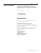
P-2 Preface Related Documentation The following documents contain additional information concerning the products discussed in this manual. For more information about: See this document: Publication number: Ethernet programmable controllers Enhanced and Ethernet PLC-5 Programmable Controllers User Manual 1785-6.5.12 Universal 1771 I/O chassis Universal I/O Chassis Installation Instructions 1771-2.
Preface Rockwell Automation Support P-3 Rockwell Automation offers support services worldwide, with over 75 sales/support offices, 512 authorized distributors, and 260 authorized systems integrators located throughout the United States alone, plus Rockwell Automation representatives in every major country in the world.
Table of Contents Overview Chapter 1 What You Need to Do . . . . . . . . . . . . . . . . . . . . . . . . . . . . . . . . . . . . . . 1-1 Identifying the Processor’s Front Panel Components . . . . . . . . . . . . . . 1-2 Components You Need . . . . . . . . . . . . . . . . . . . . . . . . . . . . . . . . . . . . . 1-4 Compliance to European Union Directives . . . . . . . . . . . . . . . . . . . . . . 1-4 EMC Directive. . . . . . . . . . . . . . . . . . . . . . . . . . . . . . . . . . . . . . . . . .
Chapter 1 Overview This quick start is designed to provide you with the information you need to get your system up and running quickly. Use this document if you are knowledgeable about Ethernet PLC-5 products, but may not have used one or more of them recently. The information we provide is geared to “jog your memory”. What You Need to Do If you need more information, see the Enhanced and Ethernet PLC-5 Programmable Controllers User Manual, publication number 1785-6.5.
1-2 Overview Identifying the Processor’s Front Panel Components These pictures show the Enhanced PLC-5 processor front panel components.
Overview 1-3 PLC-5/20E Processor Front Panel battery indicator (red when the battery is low) processor RUN/FAULT indicator (green when running; red when faulted) force indicator (amber when I/O forces are enabled) channel 0 communication status indicator (green when the channel is communicating) keyswitch; selects processor mode channel 2 Ethernet status indicator (green when functioning normally; red when not functioning) channel 2, Ethernet transmit indicator (green when the channel is communicating)
1-4 Overview Components You Need Product name: Catalog number: Hardware Ethernet PLC-5 processor with 2 keys Lithium Battery (in a clear bag) I/O chassis Power supply 1785-L20E, -L40E, -L80E 1770-XYC 1771-A1B, -A2B, -A3B, -A3B1, -A4B 1771-P4S, -P6S, -P4S1, -P6S1 Programming System PC PLC-5 programming software communication module Check your programming software documentation for system requirements, such as memory, etc.
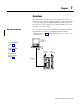
Chapter 2 Set up the Hardware 1 Install the hardware (page 2-2) 2 Connect the programming terminal and the PLC-5 processor to the communication card (page 2-6) PC with Programming Software PLC-5/20E Processor Internal Power Supply Data Highway Plus or serial cable For more information, see the Enhanced and Ethernet User Manual, publication number 1785-6.5.12. Publication 1785-10.
2-2 Set up the Hardware Install the Hardware 1 Configure the I/O Chassis Set the backplane switches. Pressed in at top ON (closed) Switch Pressed in at bottom OFF (open) Last State 1 O1 N O F F on Outputs of this I/O chassis remain in their last state when a hardware failure occurs. 1 off Outputs of this I/O chassis are turned off when a hardware failure occurs.
Set up the Hardware 2-3 2 Set the power supply configuration jumper. Are you using a power supply module in the chassis? 3 Install the keying bands. PLC-5/20 Processor Y N 2 4 6 8 10 12 14 16 18 20 22 24 26 28 30 32 34 36 38 40 42 44 46 48 50 52 54 56 Keying Bands YN O 1 N O F F 2 3 4 5 6 between - 40 & 42 - 54 & 56 7 8 20609-M For more information, see the Universal I/O Chassis installation instructions, publication number 1771-2.10.
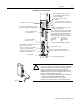
2-4 Set up the Hardware Install the Power Supply 1 Set the jumpers on the back side of the power supply like this: Locking Bar 2 Connect the power cord to the 120V ac connector of the power supply module. This side plugs into connector on the module.
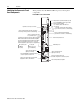
Set up the Hardware 2-5 Install the PLC-5 Processor 1 Define the DH+ Station Address of Channel 1A 2 Specify the serial communication of channel 0. by setting switch assembly SW-1. Bottom view of PLC-5/20E processor switch assembly SW2 Side View of PLC-5/20E processors SW1 Front of Processor 1234567 Always off 1 2 3 4 5 6 7 8 9 10 Side View of PLC-5/40E and -5/80E processors SW1 Bottom view of PLC-5/40E and -5/80E processor switch assembly SW2 Front of Processor 1234567 side view side view down 57.
2-6 Set up the Hardware Power Up the System Power up the system. Check the LED display on the processor. If your system is operating properly, the PROC LED should be steady red. If the PROC LED is not red, see chapter 4 for troubleshooting information before you install any I/O modules. Install the I/O Modules Locking Bar Install each I/O module and connect the wiring arm.
Chapter 3 Set up the Software 1 Install the software 2 Start the programming software 3 Powerup the system The following instructions are general. For specific information, see the documentation set for your particular software package. Install the Software and Set Up the Programming System Before you install your programming software, make certain you meet the system requirements for that software – sufficient disk space, memory, etcetera.
3-2 Set up the Software Power Up the System Power up the system if you have not done so already. Check the LED display on the processor. If your system is operating properly, the PROC LED should be steady red and the message “Processor RAM is faulted. Press to clear memory” should appear on the display. See the following table to proceed. If the PROC LED is not red, turn to chapter 4 for troubleshooting information. If your keyswitch is in this position: Publication 1785-10.
Chapter 4 Troubleshoot the Processor System 1 Use the PLC-5 Processor Status Indicators (page 4-1) BATT PROC FORCE COMM Use the PLC-5 Processor Status Indicators Troubleshoot General Problems Indicator Color Description Probable Cause Recommended Action BATT Red Battery low Battery low Replace battery within 10 days Off Battery is good Normal operation No action required Green (steady) Processor is in run mode and fully operational Normal operation No action required Green (blinkin
4-2 Troubleshoot the Processor System Indicator Color Description Probable Cause Recommended Action FORCE Amber (steady) SFC and/or I/O forces enabled Normal operation No action required Amber (blinking) SFC and/or I/O forces present but not enabled Off SFC and/or I/O forces not present Off No transmission on channel 0 Normal operation if channel is not being used Green (blinking) Transmission on channel 0 Normal operation if channel is being used COMM Troubleshoot the Processor Commu
Troubleshoot the Processor System 4-3 Troubleshoot the Ethernet Status Indicators Indicator Color Description Probable Cause Recommended Action STAT Solid red Critical hardware fault Processor requires internal repair Contact Allen-Bradley Global Technical Support (GTS) Blinking red Hardware or software fault (detected and reported via a code) Fault-code dependent Contact Allen-Bradley GTS Off Ethernet interface is functioning properly but it is not attached to an active Ethernet network N
Appendix A Specifications General This table lists general specifications. Backplane Current 3.6A Heat Dissipation 65.00 BTU/hr Environmental Conditions Operating Temperature. . . . . . . 0 to 60° C (32-140° F) Storage Temperature . . . . . . . . –40 to 85° C (–40 to 185° F) Relative Humidity . . . . . . . . . . . 5 to 95% (without condensation) Shock Operating . . . . . . 30 g peak acceleration for 11±1 ms duration Non-operating . . .
A-2 Specifications General Specifications (continued) • DH+ (trunk line: 3,048 cable-m (10,000 cable-ft); drop line: 30.4 cable-m (100 cable-ft) • DH using 1785-KA • Serial • Ethernet (TCP/IP protocol, 15-pin, AUI transceiver port) • remote I/O 1771-A1B, -A2B, A3B, -A3B1, -A4B, chassis, left-most slot Communication Location Keying Weight Agency Certification (when product is marked) Processor Specifications Processor/ Cat. No.
Specifications Battery Specification A-3 Battery Type Ethernet PLC-5 processors use 1770-XYC batteries which contain 0.65 grams of lithium. Average Battery Lifetime Specifications Worst-case Battery Life Estimates Battery used in this processor: At this temperature: Power off 100%: Power off 50%: Battery Duration after the LED lights1 PLC-5/20E 60°C 256 days 1.4 years 11.5 days 25°C 2 years 4 years 47 days 60°C 84 days 150 days 5 days 25°C 1 year 1.
A-4 Specifications CSA Hazardous Location Approval Approbation d’utilisation dans des emplacements dangereux par la CSA CSA certifies products for general use as well as for use in hazardous locations. Actual CSA certification is indicated by the product label as shown below, and not by statements in any user documentation. La CSA certifie les produits d’utilisation générale aussi bien que ceux qui s’utilisent dans des emplacements dangereux.
Allen-Bradley Publication Problem Report If you find a problem with our documentation, please complete and return this form Pub. Name Ethernet PLC-5 Programmable Controller Quick Start Cat. No. 1785-L20E, -L40E, -L80E Check Problem(s) Type: Pub. No. 1785-10.5 Pub. Date November 1998 Part No.
PLEASE FASTEN HERE (DO NOT STAPLE) PLEASE FOLD HERE NO POSTAGE NECESSARY IF MAILED IN THE UNITED STATES BUSINESS REPLY MAIL FIRST-CLASS MAIL PERMIT NO.
Publication 1785-10.5 - November 1998 Supersedes Publication 1785-10.5 - December1996 PN 955133-86 1998 Rockwell International Corp. All Rights Reserved.