Installation Instructions PLC-5 Ethernet Interface Module Catalog Number 1785-ENET, Series C, Revision B Topic Page About This Publication 1 Important User Information 2 About the Module 5 Before You Begin 15 Install the Module 16 Establish an Ethernet Connection 26 Monitor Ethernet Status Data 27 Use the Message Instruction 27 Interpret Error Codes 30 Domain Name Service 31 Embedded Web Server 32 Interpret the LED Indicators 43 Specifications 45 Additional Resources 47 About
PLC-5 Ethernet Interface Module Important User Information Solid state equipment has operational characteristics differing from those of electromechanical equipment. Safety Guidelines for the Application, Installation and Maintenance of Solid State Controls (publication SGI-1.1 available from your local Rockwell Automation sales office or online at http://literature.rockwellautomation.com) describes some important differences between solid state equipment and hard-wired electromechanical devices.
PLC-5 Ethernet Interface Module 3 Environment and Enclosure This equipment is intended for use in a Pollution Degree 2 industrial environment, in overvoltage Category II applications (as defined in IEC publication 60664-1), at altitudes up to 2000 m (6561 ft) without derating. ATTENTION This equipment is considered Group 1, Class A industrial equipment according to IEC/CISPR Publication 11.
PLC-5 Ethernet Interface Module North American Hazardous Location Approval The following information applies when operating this equipment in hazardous locations Informations sur l’utilisation de cet équipement en environnements dangereux Products marked CL I, DIV 2, GP A, B, C, D are suitable for use in Class I Division 2 Groups A, B, C, D, Hazardous Locations and nonhazardous locations only.
PLC-5 Ethernet Interface Module 5 European Hazardous Location Approval European Zone 2 Certification (The following applies when the product bears the EEx marking.) This equipment is intended for use in potentially explosive atmospheres as defined by European Union Directive 94/9/EC.
PLC-5 Ethernet Interface Module PLC-5 Series/Revision Compatibility Series Revision Controller E and later Any All Enhanced, Ethernet, and ControlNet PLC-5 controllers D B PLC-5/11, PLC-5/20, PLC-5/26, PLC-5/30, PLC-5/40, PLC-5/40L, PLC-5/46, PLC-5/60, PLC-5/60L, PLC-5/80, PLC-5/86 PLC-5/20E, PLC-5/40E, PLC-5/80E PLC-5/20C, PLC-5/40C, PLC-5/80C C K PLC-5/11, PLC-5/20, PLC-5/26, PLC-5/30, PLC-5/40, PLC-5/40L, PLC-5/46, PLC-5/60, PLC-5/60L, PLC-5/80, PLC-5/86 PLC-5/20E, PLC-5/40E, PLC-5/80E PLC
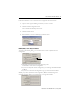
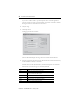
PLC-5 Ethernet Interface Module 7 Follow these directions to see or activate the new configuration and status features: 1. Open or create a project in RSLogix 5 software, version 7.1 or later. 2. Click the Channel Configuration menu. You see the Edit Channel Properties screen. 3. Click the Channel 3A tab. 4. Select Ethernet/C from the Channel Type pull-down menu. BOOTP, DHCP, or Static Entry of IP Address As shown in the following dialog, you can select between a static or dynamic network configuration.
PLC-5 Ethernet Interface Module When you create a hostname, consider these naming conventions. • The hostname can be a text string up to 24 characters. • The hostname can contain alphanumeric (A through Z, 0...9) and may contain a period and minus sign. • The first character must be an alpha character. • The last character must not be a minus sign. • You cannot use blank spaces or space characters. • The hostname is not case-sensitive.
PLC-5 Ethernet Interface Module 9 Unchecked Autonegotiate Checkbox and Corresponding Port Settings Checked Autonegotiate Checkbox and Corresponding Port Settings Email Client Functionality The controller is an email client that sends an email triggered by a message instruction via a mail relay server. The controller uses standard SMTP protocol to forward the email to the relay server. The controller does not receive email.
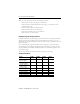
PLC-5 Ethernet Interface Module If you want to send an email to a specific recipient when a controller application generates an alarm or reaches a certain condition, program the controller to send the message instruction to the destination of the email. 2. Verify the rung. 3. Click Setup Screen. A dialog appears like the one below. The three Data fields display the string values of the ST file element addresses. 4.
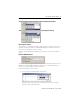
PLC-5 Ethernet Interface Module Error Code (hex) Description 0x105 Communication error with SMTP server. 0x106 Authentication required. 0x017 Authentication failed. 11 Channel 3A Status Follow these directions to check the status of channel 3A: 1. Click Channel Status in your RSLogix 5 software project. You see the Channel Status menu. 2. Click the Channel 3A tab. 3. Click the Port tab. You see the status for each port configuration.
PLC-5 Ethernet Interface Module Enable/Disable HTTP Web Server You can disable the HTTP Web server functionality from within the Channel 3A Configuration by unchecking the HTTP Server Enable checkbox shown below. The default (checked box) lets you connect to the controller using a Web browser.
PLC-5 Ethernet Interface Module 13 Web Diagnostics and Module Information This enhancement is a user-friendly tabularized view of Web diagnostics and module information. Web User-provided Pages (WUPP) WUPP lets you create your own custom Web pages to provide executive summaries of process information. The Web pages can contain data table elements, text, and images. These pages are accessible to any Internet user who has network access to the PLC-5 controller.
PLC-5 Ethernet Interface Module The additional diagnostics are available for use within a user program as words 44...49 of the Ethernet diagnostic file: Word 44 45...47 48...49 Displays Not used Ethernet hardware address Assigned Internet protocol (IP) ddress Words 45...47 contain the six-digit Ethernet hardware address. For example, if the Ethernet hardware address is 00:00:BC:03:00:1D, words 45...47 would contain 000 BC03 001D.
PLC-5 Ethernet Interface Module 15 Before You Begin Follow these directions before installing your module: 1. Check your Ethernet interface module package. 2. Make certain that you have the following items: Quantity Description 1 1785-ENET Ethernet Interface Module 1 Connector kit containing 1 PLC-5 controller 58-pin connector header 1 Industrial Automation Wiring and Grounding Guidelines, publication 1770-4.
PLC-5 Ethernet Interface Module Parts List Required Tools The 1785-ENET is a modular component of the 1771 I/O system requiring a properly installed system chassis. Refer to Universal Chassis I/O Installation Instructions, publication 1771-IN075, for detailed information on an acceptable chassis along with proper installation and grounding requirements. Limit the maximum adjacent slot power dissipation to 10 W.
PLC-5 Ethernet Interface Module 17 3. Install the combination into the chassis. IMPORTANT If your power supply is already installed in the chassis, be sure the power supply is OFF before you install the module. If you install the module with power ON, you will damage the module. Attach the Connector Header to the Controller With grounding wrist strap attached to your wrist, follow these steps: 1. Locate the controller’s connector header port. 2. Push the exposed pins into the holes on the controller.
PLC-5 Ethernet Interface Module Connect the Module to the Controller 1. Align the pins and holes on the module to those on the connector header. 2. Press the module into the connector header. 3. Tighten the screws. IMPORTANT Make certain you carefully align the pins and holes together before you press the connector header into the controller. Improper alignment will bend the connector header pins.
PLC-5 Ethernet Interface Module 19 Install the Module Combination into the Chassis With grounding wrist strap attached to your wrist, follow these steps: 1. Make certain the power to the chassis is OFF. 20615 2. Raise the locking bar. 20616 3. Insert the module combination into the leftmost slots of the chassis.
PLC-5 Ethernet Interface Module 4. Lower the locking bar into place. 20617 Configure the Module for Ethernet Communication Before configuring channel 3A for Ethernet communication, be sure to: • know the Ethernet hardware address. • assign an IP address to the module. Because the module uses the TCP/IP protocol, each Ethernet hardware address on the network requires a unique IP address.
PLC-5 Ethernet Interface Module 21 Use your programming software package to designate channel 3A as the channel that supports the module if you are configuring offline (if you are configuring online, designation is automatic). IMPORTANT To configure the module online, it must be attached to the controller.
PLC-5 Ethernet Interface Module Enter configuration information in the appropriate fields. This Field Specifies Diagnostics file The file containing the channel’s status information Configure by Doing the Following Cursor to the field, type an unused integer file number (10...999), and press Enter. The system creates an integer file 44 words long. Important: Do not assign a diagnostic file number that is the I/O status file you assigned to another communication channel or any other used file.
PLC-5 Ethernet Interface Module 23 This Field Specifies Configure by Doing the Following Inactivity timeout The number of minutes of inactivity before the connection is closed Cursor to the field, and enter a timeout period in minutes. The valid range for a timeout period is 0...65,535 minutes. The default is 30 minutes.
PLC-5 Ethernet Interface Module With all hardware and IP addresses in one location, you can easily change IP addresses in the BOOTP configuration file if your network needs change. Edit the BOOTPTAB Configuration File IMPORTANT Be certain you know your Ethernet hardware address as you will enter it in this file. You must edit the BOOTPTAB file, which is an ASCII text file, to include the name, IP address, and hardware address for each Ethernet interface module you want the server to boot.
PLC-5 Ethernet Interface Module EXAMPLE 25 The following system shows three controllers (two enhanced controllers and one Ethernet controller) with attached 1785–ENET interface modules and a workstation with a BOOTP server. The names and hardware addresses are device specific.
PLC-5 Ethernet Interface Module Based on this configuration, the BOOTPTAB file would look like this: # # Legend: gw -- gateways ha -- hardware address # # # ht -- hardware type(1) ip -- host IP address sm -- subnet mask # # vm -- BOOTP vendor extensions format(2) tc -- template host #Default string for each type of Ethernet client defaults5E: ht=1:vm=rfc1048 #Entries device1: device2: device4: for 1785-ENET modules: tc=defaults5E:ip=12.34.56.1:ha=0000BC031234 tc=defaults5E:ip=12.34.56.
PLC-5 Ethernet Interface Module 27 Monitor Ethernet Status Data Monitor communication status through the module by accessing the Ethernet Channel 3A status dialog. Ethernet Status Data Status Field Commands Replies Ethernet Bytes Displays the Number of Sent 0...3 Commands sent by the channel Received 4...7 Commands received by the channel Sent 8...11 Replies sent by the channel Received 12...15 Replies received by the channel Sent with error 16...
PLC-5 Ethernet Interface Module The MSG instruction transfers data in packets. Each packet can contain up to 709 words for Ethernet controllers and interface modules. If your message transfer contains more words than fit in one packet, the transfer requires more than one packet of transfer data. The more packets of data to transfer, the longer the total transfer takes. Enter Parameters The control block is where all of the information relating to the message is stored.
PLC-5 Ethernet Interface Module 29 The IP address specifies the MSG instruction’s destination node. If the destination is: • a PLC-5/20E, PLC-5/40E, PLC-5/80E, or another 1785-ENET-equipped PLC-5 controller, the destination must be a full IP address. • an INTERCHANGE client program, type CLIENT in the Destination Node field. IMPORTANT You must set the port number to 3A to access this function.
PLC-5 Ethernet Interface Module Interpret Error Codes When the controller/interface module detects an error during the transfer of message data, the controller sets the .ER bit and enters an error code that you can monitor from your programming software.
PLC-5 Ethernet Interface Module Code (Hexadecimal - word 1 of the control block) Description (displayed on the data monitor screen) F002 Incomplete address F003 Incorrect address F006 Addressed file does not exist in target controller F007 Destination file is too small for number of words requested F00A Target controller cannot put requested information in packets F00B Privilege error, access denied F00C Requested function is not available F00D Request is redundant F011 Data type request
PLC-5 Ethernet Interface Module With the latest release of the Ethernet PLC-5 controllers and RSLogix programming software, version 5.20 or later, you can enter the symbolic form of the IP address as the IP address in the Message Block. The Channel Configuration feature in RSLogix5 programming software lets you configure a primary and secondary DNS server, as well as a default domain name (for example, cle.ab.com). DNS names consist of a label name and a domain name.
PLC-5 Ethernet Interface Module 33 This page displays general messaging statistics. Use the information on this page when troubleshooting the network.
PLC-5 Ethernet Interface Module The second list contains Application Level Statistics.
PLC-5 Ethernet Interface Module 35 To change the refresh data function back to the default of 15 seconds, click the Default field. To disable the refresh data function, click the Disable button. Generate Web User-provided Pages You can use a text editor to generate up to 16 Web user-provided pages. The pages are stored in consecutive ASCII files of the controller. The channel-configuration feature of RSLogix 5 software, version 5.20 or later, lets you select the starting file and number of files used.
PLC-5 Ethernet Interface Module • %format - legal values are %d for decimal and %x for hexadecimal. The following file types allow the format to be specified: • Input • Output • Status • Integer • Timer • Counter • MSG • BT • Control • BCD • PID • SFC • Display format defaults - Input and Output file elements are output in octal format. Status and BCD file elements are output in hexadecimal format with a leading 0x. Integer file elements are output in decimal format.
PLC-5 Ethernet Interface Module 37 Generate Custom Data Table Monitor Pages You can generate Custom Data Table Monitor pages with your text editor then download them to the controller. The first element of the file must contain a special tag as follows: where xx is the automatic refresh rate in seconds (01...99). A value outside the range defaults to a snapshot display.
PLC-5 Ethernet Interface Module All other file types are displayed in an appropriate format. If a % format modifier is present, the format may be changed by clicking on the file type/number via a Web browser. • #expand - legal values are #c and #e. This modifier determines whether the structure file types are displayed in their expanded or compacted formats. If a # modifier is present, the format may be changed by clicking on the [+]/[-] via a Web browser.
PLC-5 Ethernet Interface Module 39 13. Click +A22. You can change the radix display of N7:0 through N7:2. 14. Go back to the Custom Data Table Monitor page. 15. Click N:70 in the Address column to display the radix selection page. 16. Click the desired radix type radio button. Follow these directions to see the Sample Extended Format page: 1. Go back to the Custom Data Table Monitor page. 2. Click + before the T4:0 in the Address column to display the Sample Extended Format.
PLC-5 Ethernet Interface Module Group MIB Description Interfaces ifIndex Interface number ifDescr Description of the interface ifType Type of interface ifMTU MTU size ifSpeed Transmission rate in bits/second ifPhysAddress Media specific address ifAdminStatus Desired interface state ifOperStatus Current interface state ifLastChange How long ago interface changes state ifInOctets Total octets received from the data ifUcasPackets Broadcast/multicast packets delivered above ifInDi
PLC-5 Ethernet Interface Module Group MIB Description IP ipForwarding Acting as a gateway or host ipDefaultTTL Default TTL for IP packets ipInReceives Total datagrams from below ipInHdrErrors Datagrams discarded due to format errors ipInAddrErrors Datagrams discarded due to misdelivery ipForwDatagrams Datagrams forwarded ipUnknownProtos Datagrams destined for unknown protocols ipInDiscards Datagrams discarded due to resource limitations ipInDelivers Datagrams delivered above ipOutRequ
PLC-5 Ethernet Interface Module Group MIB Description IP ipRouteProto Mechanism used to determine route ipRouteAge Age of route in seconds ipRouteMask Subnet mask for route ipNetToMediaflIndex Interface number ipNetToMediaPhysAddre Media address of mapping ss ipNetToMediaNetAddres IP address of mapping s ipNetToMediaType How mapping was detemined ipReasmReqds Fragments received needing reassembly ipReasmOKs Datagrams successfully reassembled ipReasmFails Reassembly failure ipFragOKs
PLC-5 Ethernet Interface Module Group MIB Description TCP tcpInSegs Number of segments received tcpOutSegs Number of segments sent tcpRetransSegs Number of segments retransmitted tcpInErrors Number of segments discarded due to format errors tcpOutRsts Number of resets generated tcpConnState State of connection tcpConnLocalAddress Local IP address tcpConnLocalPort Local TCP port tcpConnRemAddress Remote IP address tcpConnRemPort Remote TCP port 43 Interpret the LED Indicators If you
PLC-5 Ethernet Interface Module Monitor the series of blinks to determine the fault code. Count the first and last series of slow blinks, and disregard the series of fast blinks between the slow series. IMPORTANT The interface module will flash the indicator lights as shown in the Module Error Codes table. The controller may fault even though the module does not.
PLC-5 Ethernet Interface Module 45 Controller Fault Codes Fault Code Description 91 Module undefined message type. 92 Module requesting undefined pool. 93 Module illegal maximum pool size. 94 Module illegal ASCII message. 95 Module reported fault, in which a bad program causes memory corrupt, or, of a hardware failure. 96 Module not physically connected to the controller. 97 Module requested a pool size that is too small for PCC command (occurs when cycling power).
PLC-5 Ethernet Interface Module Environmental Specifications Attribute Value Operating Temperature IEC 60068-2-1 (Test Ad, Operating Cold), IEC 60068-2-2 (Test Bd, Operating Dry Heat), IEC 60068-2-14 (Test Nb, Operating Thermal Shock): 0...60 oC (32...140 oF) Storage Temperature IEC 60068-2-1 (Test Ab, Unpackaged Nonoperating Cold), IEC 60068-2-2 (Test Bc, Unpackaged Nonoperating Dry Heat), IEC 60068-2-14 (Test Na, Unpackaged Nonoperating Thermal Shock): –40...85 oC (–40...
PLC-5 Ethernet Interface Module 47 Certifications Certification Value Certifications(1) (when product is marked) UL CSA (1) UL Listed Industrial Control Equipment. See UL File E65584. CSA Certified Process Control Equipment. See CSA File R54689C. CSA CSA Certified Process Control Equipment for Class I, Division 2 Group A,B,C,D Hazardous Locations. See CSA File LR69960C. CE European Union 89/336/EEC EMC Directive, compliant with: EN 50082-2; Industrial Immunity EN 61326; Meas./Control/Lab.
Rockwell Automation Support Rockwell Automation provides technical information on the web to assist you in using its products. At http://support.rockwellautomation.com, you can find technical manuals, a knowledge base of FAQs, technical and application notes, sample code and links to software service packs, and a MySupport feature that you can customize to make the best use of these tools.