
Manual

Installation Data
Enhanced PLC5 and Ethernet PLC5
Programmable Controller Memory Module
9
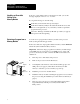
Important: You can have continuous processor memory backup after
restoring a program from a memory module to a processor by following
these instructions:
1. Turn off power to the processor and I/O chassis.
2. Remove the memory module by following the removal procedure in
this document (see page 5).
3. Remove the write protection jumper with needle nose pliers to guard
against unauthorized changes. Store the jumper in a safe place for
future use.
4. Re-install the memory module into the processor by following the
installation procedure in this document (see page 5).
5. Remove the processor from the I/O chassis.
6. Set switch 6 and 7 of the assembly backplane switches to the ON
position (see page 4).
7. Re-install the processor into the I/O chassis.
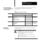
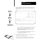
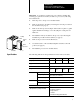
The following table shows the specifications for the memory modules.
Memory Module 1785ME16 1785ME32 1785ME64 1785M100
Capacity 16K words 32K words 64K words 100K words
Type Nonvolatile
Write Protection By removing the jumper
Weight 85.05 g
3 oz
70.875 g
2.5 oz
70.875 g
2.5 oz
70.875 g
2.5 oz
Environment
Operating Temperature
0° to 60° C (32° to 140° F)
Storage Temperature
40° to 85° C (40° to 185° F)
Relative Humidity 5 to 95% (without condensation)
Shock Testing
Operating 15 g peak acceleration at 11 ms duration
Nonoperating 3 g peak acceleration at 11 ms duration
Vibration Testing 2 g peak acceleration at 10500 Hz
Agency Certification
(when product or package is marked)
• CSA certified
• CSA Class I, Division 2
Groups A, B, C, D
• UL listed
• CE marked for all applicable directives
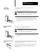
19633
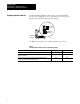
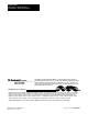
PLC5
processor
Ejector
Tab
Locking
Bar
Card Guides
Specifications