
Manual

19632
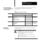
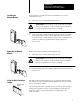
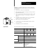
Locking
Bar
Ejector
Tab
PLC5
processor
Card Guides
Installation Data
PLC5/11, 5/20, 5/30, 5/40, 5/40L, 5/60
Programmable Controller Memory Module
Installation Data
Enhanced PLC5 and Ethernet PLC5
Programmable Controller Memory Module
6
Use the following steps to store a program on your memory module.
Important: If you are using a 1785-L40B series A, revision B or a
1785-L60B series A, revision B processor, you must have the Global
Status Flag file set to zero. Access this file through the channel
configuration screen for channels configured for DH+ communications. If
the Global Status Flag file is set to any number except zero and you try to
write to a memory module, you will lose processor memory and a
processor fault occurs.
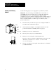
1. Insert the memory module into the processor using the installation
procedure in this document (see page 5).
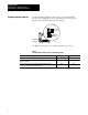
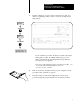
2. On the I/O chassis backplane, set backplane switch 6 to the ON
position and switch 7 to the OFF position (see page 4).
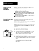
3. Install the processor into the I/O chassis.
4. Turn on power to the processor and I/O chassis.
5. Put the processor in Program or Rem Program mode.
If you try to write to a memory module when the processor is in any
other mode, you receive a
NO ACCESS OR PRIVILEGE
VIOLATION message.
6. Develop or download your program online (make sure you initialize
your data table values).
Writing to the Memory
Module
18593