
Manual

Installation Data
Enhanced PLC5 and Ethernet PLC5
Programmable Controller Memory Module
5
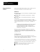
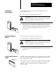
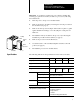
Insert the memory module into the front of the PLC-5 processor by
following these steps:
1. Turn off power to the I/O chassis and processor.
ATTENTION: Do not insert or remove the memory module
under power. Insertion or removal under power can result in
loss of program memory and a processor fault.
2. Insert the memory module firmly but gently into the processor with
the keying pin in the down position. When the memory module is
inserted correctly you will hear the connector pins on the back of the
memory module snap together with the mating connector in
the processor.
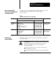
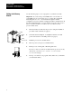
Remove the memory module by following these steps:
1. Turn off power to the I/O chassis and processor.
ATTENTION: Do not insert or remove the memory module
under power. Insertion or removal under power can result in
loss of program memory and a processor fault.
2. Grasp the finger grip tabs and firmly pull the memory module out of
the processor.
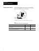
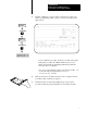
The write protection jumper allows you to program the memory module.
The memory module is packaged with the jumper in the correct position to
write to the memory module.
After writing to the memory module, remove the write protection jumper
using a pair of needle nose pliers. Store the jumper in a safe place for
future use. Once you remove the jumper, you cannot write to the
memory module.
Installing the
Memory Module
18590
Keying pin
Removing the Memory
Module
18591
Keying pin
Using the Write Protection
Jumper
18592
Write protection
jumper