
Manual

Installation Data
PLC5/11, 5/20, 5/30, 5/40, 5/40L, 5/60
Programmable Controller Memory Module
Installation Data
Enhanced PLC5 and Ethernet PLC5
Programmable Controller Memory Module
4
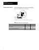
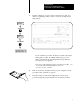
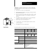
Set the I/O chassis backplane switches before you install the PLC-5
processor. Use a ballpoint pen to set each switch (do not use a pencil
because the tip can break off and short the switch).
18594
ON (Closed)
OFF (Open)
Backplane
Switches
Backplane
switches
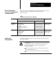
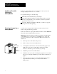
Use Table 2 to select the mode of memory transfer at power-up.
Table 2
Selecting
Mode of Memory Transfer and Switch Settings
If you want the contents of the memory module: Then set switch 6: And set switch 7:
to transfer to processor memory at every powerup OFF OFF
to transfer to processor memory when a defect is detected in existing
processor memory
ON ON
not to transfer to processor memory at powerup; if the processor
memory is not valid, a processor fault occurs.
ON OFF
Setting Backplane Switches