Installation Instructions Ethernet PLC-5 Programmable Controllers Catalog Numbers 1785-L20E, 1785-L40E, 1785-L80E, Series F Contents About This Publication For This Topic See Page About This Publication 1 Related User Manual 5 About the Controllers 6 Install the System Hardware 13 Troubleshoot the Controller 20 Controller Specifications 24 Rockwell Automation Support Back cover This document describes how to install and troubleshoot your Ethernet PLC-5 programmable controller.
Ethernet PLC-5 Programmable Controllers Important User Information Solid state equipment has operational characteristics differing from those of electromechanical equipment. Safety Guidelines for the Application, Installation and Maintenance of Solid State Controls (Publication SGI-1.1 available from your local Rockwell Automation sales office or online at http://www.ab.com/manuals/gi) describes some important differences between solid state equipment and hard-wired electromechanical devices.
Ethernet PLC-5 Programmable Controllers 3 Environment and Enclosure ATTENTION • This equipment is intended for use in a Pollution Degree 2 industrial environment, in overvoltage Category II applications (as defined in IEC publication 60664-1), at altitudes up to 2000 meters without derating. • This equipment is considered Group 1, Class A industrial equipment according to IEC/CISPR Publication 11.
Ethernet PLC-5 Programmable Controllers North American Hazardous Location Approval The following information applies when operating this equipment in hazardous locations: Informations sur l’utilisation de cet équipement en environnements dangereux : Products marked “CL I, DIV 2, GP A, B, C, D” are suitable for use in Class I Division 2 Groups A, B, C, D, Hazardous Locations and nonhazardous locations only.
Ethernet PLC-5 Programmable Controllers Related User Manual 5 The related user manual contains detailed information about configuring, programming, and using an Ethernet PLC-5 controller. To obtain a copy of the Enhanced and Ethernet PLC-5 Programmable Controllers User Manual, publication 1785-UM012, you can: • view or download an electronic version from the Internet at www.rockwellautomation.com/literature. • contact your local distributor or Rockwell Automation representative to place an order.
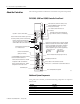
Ethernet PLC-5 Programmable Controllers About the Controllers The following illustrations indicate the controller’s front panel components.
Ethernet PLC-5 Programmable Controllers 7 New Features The controllers contain an RJ-45 connector for the Channel 2 communication port.
Ethernet PLC-5 Programmable Controllers Similarly, if you have a dynamic network configuration, DHCP or BOOTP assigns the controller’s hostname. With a static configuration, you assign the hostname. When you create a hostname, consider these naming conventions. • The hostname can be a text string up to 24 characters. • The hostname can contain alpha (A to Z) numeric (0 to 9) and may contain a period and minus sign. • The first character must be an alpha character.
Ethernet PLC-5 Programmable Controllers 9 The unchecked Auto Negotiate box and corresponding port settings are shown below. The checked Auto Negotiate box and corresponding port settings are shown below. Email Client Functionality The controller is an email client that sends an email triggered by a message instruction via a mail relay server. The controller uses standard SMTP protocol to forward the email to the relay server. The controller does not receive email.
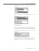
Ethernet PLC-5 Programmable Controllers To create an email: 1. Create a message instruction similar to the one below. The destination (to), the reply (from), and the body (text) are stored as strings in elements of separate ASCII string files. If you want to send an email to a specific recipient when a controller application generates an alarm or reaches a certain condition, program the controller to send the message instruction to the destination of the email. 2. Verify the rung. 3.
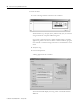
Ethernet PLC-5 Programmable Controllers 11 4. To send email, enter the appropriate information into the Data fields and Username and Password, if Authentication is enabled. Examine the Error Code (denoted in Hex) and Error Description areas within the General tab to see if the message was successfully delivered. Error Code (hex) Description 0x000 Delivery successful to the mail relay server. 0x002 Resource unavailable.
Ethernet PLC-5 Programmable Controllers Enable/Disable HTTP Web Server You can disable the HTTP web server functionality from within the Channel 2 Configuration by unchecking the HTTP Server Enable check box shown below. SNMP Server Enabled HTTP Server Enabled The default (checked box) lets you connect to the controller using a web browser.
Ethernet PLC-5 Programmable Controllers Install the System Hardware 13 This illustration shows a basic Ethernet PLC-5 programmable controller system. PC with Programming Software Ethernet PLC-5 Controller Internal Power Supply Data Highway Plus or Serial Cable 43910 For more information, see the Enhanced and Ethernet PLC-5 Programmable Controllers User Manual, publication 1785-UM012.
Ethernet PLC-5 Programmable Controllers Prepare to Install the Controller Installing the controller is one part of setting up the hardware in your system. To properly install the controller, you must follow these procedures in the order described in this section. 1. Install an I/O Chassis. 2. Configure the I/O Chassis. 3. Install the Power Supply. 4. Install the PLC-5 Programmable Controller. 5. Apply Power to the System. 6. Connect the Personal Computer to the PLC-5 Programmable Controller.
Ethernet PLC-5 Programmable Controllers 15 Configure the I/O Chassis Configure the I/O chassis by following this procedure. 1. Set the backplane switches. Pressed In At Top ON (closed) Pressed In At Bottom OFF (open) Switch 1 Last State 1 O1 N O F F on Outputs of this I/O chassis remain in their last state when a hardware failure occurs. (1) off Outputs of this I/O chassis are turned off when a hardware failure occurs.
Ethernet PLC-5 Programmable Controllers 2. Set the power-supply configuration jumper and set the keying bands as shown below. Are you using a power supply module in the chassis? Y N Keying Bands YN 2 4 6 8 10 12 14 16 18 20 22 24 26 28 30 32 34 36 38 40 42 44 46 48 50 52 54 56 Between - 40 & 42 - 54 & 56 43912 Install the Power Supply Install a power supply according to one of the following corresponding installation instructions.
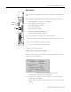
Ethernet PLC-5 Programmable Controllers 17 Install the PLC-5 Programmable Controller The controller is a modular component of the 1771 I/O system requiring a properly installed system chassis. Refer to publication 1771-IN075 for detailed information on acceptable chassis along with proper installation and grounding requirements. Limit the maximum adjacent slot power dissipation to 10 W. 1. Define the DH+ Station Address of Channel 1A by setting switch assembly SW-1 on the back of the controller.
Ethernet PLC-5 Programmable Controllers 3. To install the battery, attach the battery-side connector into the controller-side connector inside the battery compartment of the controller. Locking Bar Ejector Tab Battery Connector is Mounted Inside the Battery Compartment Card Guides Battery 43916 WARNING When you connect or disconnect the battery, an electrical arc can occur. This could cause an explosion in hazardous location installations.
Ethernet PLC-5 Programmable Controllers 19 See the following table to proceed. If the PROC LED is not off, turn to the next page for troubleshooting information. If Your Keyswitch is in This Position Do This PROGRAM Clear memory. The PROC LED should turn off. The software is in Program mode. REMOTE Clear memory. The PROC LED should turn off. The software is in Remote Program mode. RUN You see the message No access or privilege violation because you cannot clear memory in Run mode.
Ethernet PLC-5 Programmable Controllers Connect the Personal Computer to the PLC-5 Programmable Controller For more information, see: • Enhanced and Ethernet PLC-5 Programmable Controllers User Manual, publication 1785-UM012 • the documentation provided with your communication card • Data Highway/Data Highway Plus/Data Highway II/Data Highway 485 Cable Installation Manual, publication 1770-6.2.
Ethernet PLC-5 Programmable Controllers 21 Indicator Color Description Probable Cause Recommended Action PROC Red Fault with memory loss New controller Use programming software to clear and initialize memory Processor has failed internal diagnostics Install battery (to preserve failure diagnostics), then power down, reseat controller and cycle power; then reload your program. If you are unable to reload your program, replace the controller.
Ethernet PLC-5 Programmable Controllers Troubleshoot the Controller Communication Channels A Indicator Color Channel Mode Description Probable Cause Recommended Action A or B Green (steady) Remote I/O Scanner Active Remote I/O link, all adapter modules are present and not faulted Normal operation No action required Remote I/O Adapter Communicating with scanner DH+ Controller is transmitting or receiving on DH+ link Remote I/O Scanner At least one adapter is faulted or has failed Pow
Ethernet PLC-5 Programmable Controllers 23 Troubleshoot the Ethernet Status Indicators ENET Status Indicator Color Description Probable Cause Recommended Action STAT Solid red Critical hardware fault Controller requires internal repair Contact your local Allen-Bradley distributor Blinking red Hardware or software fault (detected and reported via a code) Fault-code dependent Contact Technical Support at 440.646.3223 to diagnose the problem.
Ethernet PLC-5 Programmable Controllers Controller Specifications Operating Temperature IEC 60068-2-1 (Test Ad, Operating Cold), IEC 60068-2-2 (Test Bd, Operating Dry Heat), IEC 60068-2-14 (Test Nb, Operating Thermal Shock): 0...60 oC (32...140 oF) Nonoperating Temperature IEC 60068-2-1 (Test Ab, Un-packaged Nonoperating Cold), IEC 60068-2-2 (Test Bc, Un-packaged Nonoperating Dry Heat), IEC 60068-2-14 (Test Na, Un-packaged Nonoperating Thermal Shock): –40...85 oC (–40...
Ethernet PLC-5 Programmable Controllers 25 Controller Specifications (continued) Time-of-day Clock/Calendar(1) Available Cartridges Memory Modules I/O Modules Hardware Addressing Location Weight Certifications(2) (when product is marked) Maximum Variations at 60× C: ± 5 min per month Typical Variations at 20× C: ± 20 s per month Timing Accuracy: 1 program scan 1785-RC Relay Cartridge • 1785-ME16 • 1785-ME32 • 1785-ME64 • 1785-M100 Bulletin 1771 I/O, 1794 I/O, 1746 I/O, and 1791 I/O including 8-, 16-, 3
Ethernet PLC-5 Programmable Controllers Battery Type Ethernet PLC-5 programmable controllers use 1770-XYC batteries that contain 0.65 grams of lithium. Average Battery Lifetime Specifications Worst-case Battery Life Estimates In This Controller: At This Temperature Power Off 100% Power Off 50% Battery Duration After The LED lights(1) PLC-5/20E, -5/40E, -5/80E 60 °C 84 days 150 days 5 days 25 °C 1 year 1.2 years 30 days (1)The battery indicator (BATT) warns you when the battery is low.
Ethernet PLC-5 Programmable Controllers 27 Notes Publication 1785-IN063B-EN-P - January 2006
Rockwell Automation Support Rockwell Automation provides technical information on the web to assist you in using our products. At http://support.rockwellautomation.com, you can find technical manuals, a knowledge base of FAQs, technical and application notes, sample code and links to software service packs, and a MySupport feature that you can customize to make the best use of these tools.