ControlNet PLC-5 Programmable Controllers Catalog Numbers 1785-L20C15, -L40C15, -L46C15, -L80C15 Quick Start
Important User Information Because of the variety of uses for the products described in this publication, those responsible for the application and use of these products must satisfy themselves that all necessary steps have been taken to assure that each application and use meets all performance and safety requirements, including any applicable laws, regulations, codes and standards.
ATTENTION ! Environment and Enclosure This equipment is intended for use in a Pollution Degree 2 industrial environment, in overvoltage Category II applications (as defined in IEC publication 60664-1), at altitudes up to 2000 meters without derating. This equipment is considered Group 1, Class A industrial equipment according to IEC/CISPR Publication 11.
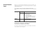
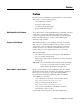
Rockwell Automation Support Before you contact Rockwell Automation for technical assistance, we suggest you please review the troubleshooting information contained in this publication first. If the problem persists, call your local Rockwell Automation representative or contact Rockwell Automation in one of the following ways: Phone Internet United States/Canada 1.440.646.5800 Outside United States/Canada You can access the phone number for your country via the Internet: 1. Go to http://www.ab.com 2.
Preface Preface Read this preface to familiarize yourself with the rest of the manual. This preface covers the following topics: • who should use this manual • the purpose of this manual • conventions used in this manual • Rockwell Automation support Who Should Use this Manual To use this manual, you should understand programmable controllers and be able to interpret the ladder logic instructions required to control your application.
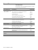
P-6 Preface Related Documentation The following documents contain additional information concerning the products discussed in this manual. For more information about: See this publication: Publication number: ControlNet PLC-5 programmable controllers (1785-L20C15, -L40C15, -L46C15 and -L80C15) ControlNet PLC-5 Programmable Controllers User Manual 1785-UM022 Enhanced and Ethernet PLC-5 Programmable Controllers User Manual 1785-6.5.12 1785 Enhanced PLC-5 Processor System Overview 1785-2.
Preface Conventions Used in This Manual P-7 The following conventions are used throughout this manual: • Bulleted lists provide information, not procedural steps. • Numbered lists provide sequential steps or hierarchical information. • Italic type is used for emphasis. • Text in this font indicates words or phrases you should type. • Key names match the names shown and appear in bold, capital letters (for example, ENTER). Tip: We use this convention to call attention to helpful information.
P-8 Preface Notes Publication 1785-QS006C-EN-P - April 2002
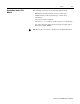
Table of Contents Before You Begin Set Up the Hardware Set Up the Software Troubleshoot the Processor System Specifications Chapter 1 What You Need to Do . . . . . . . . . . . . . . . . . . . . . . . . . . . . . . . . . . . . . . 1-1 Identify the Processor’s Front Panel Components. . . . . . . . . . . . . . . 1-2 Check Your Components. . . . . . . . . . . . . . . . . . . . . . . . . . . . . . . . . . . . 1-3 Compliance to European Union Directives . . . . . . . . . . . . . . . . . . . . . .
toc–ii Table of Contents – Quick Start Notes Publication 1785-QS006C-EN-P - April 2002
Chapter 1 Before You Begin The ControlNet network is a high-speed link that lets PLC processors and I/O devices (e.g., I/O racks, variable speed drives, Man-Machine Interface (MMI), and other automation devices) exchange data. The ControlNet PLC-5 processors have one logical ControlNet port consisting of two BNC connectors and one network access port; these processors let you connect to the ControlNet network.
1-2 Before You Begin Identify the Processor’s Front Panel Components These pictures show the ControlNet PLC-5 processor front panel components.
Before You Begin Check Your Components 1-3 For this quick start, you need this hardware and software: Product name: Catalog number: Hardware ControlNet PLC-5 processor 1785-L20C15, -L40C15, -L46C15, -L80C15 ControlNet network access cable 1786-CP 1771 I/O chassis 1771-A1B power supply 1771-P4S personal computer communication interface card 1784-KTCX15 Software RSLogix5 programming software 1 • 9324-RL5300END (diskettes) • or 9324-RL5300ENE (CDROM) RSNetWorx network configuration software 1
1-4 Before You Begin Notes Publication 1785-QS006C-EN-P - April 2002
Chapter 2 Set Up the Hardware 1 Install the hardware (page 2-2) PC with Programming Software the personal computer to 2 Connect the PLC-5 processor (page 2-6 PLC-5/20C Processor ControlNet network access cable (1786-CP) or serial cable (1784-CP10) Internal Power Supply For more information, see the ControlNet PLC-5 Programmable Controllers User Manual, publication number 1785-UM022.
2-2 Set Up the Hardware Install the Hardware Configure the I/O Chassis switches. 1 SetSetthethebackplane backplane switches. Pressed in at top ON (closed) Switch Pressed in at bottom OFF (open) Last State 1 O1 N O F F on Outputs of this I/O chassis remain in their last state when a hardware failure occurs. 1 off Outputs of this I/O chassis are turned off when a hardware failure occurs.
2-3 Set Up the Hardware Set the the power 2 Set powersupply supply configuration jumper. configuration jumper. Are you using a power supply module in the chassis? Install the keying keyingbands. bands.
2-4 Set Up the Hardware Install the Power Supply To install the power supply, refer to one of the publications listed below: To install one of these power supplies: See this publication: Publication number: 1771-P4S, -P6S, -P4S1, -P6S1 1771-P4R, -P64 1771-P7 Power Supply Modules Installation Data Redundant Power Supply Modules Installation Instructions AC Power Supply Installation Instructions 1771-2.135 1771-5.
2-5 Set Up the Hardware 1 Define the DH+ Station Address of Channel 1A by setting switch assembly SW-1 on the back of the processor. (See the side of the processor if you want to use another address.) Locking Bar side view of processor Lift Ejector Tab PLC-5/20 Processor 1 2 3 4 5 6 7 Battery Connector Battery Cover side view down 57.
2-6 Set Up the Hardware Install the I/O Modules Locking Bar Install each I/O module and connect the wiring arm. Refer to the user documentation you recieved with the I/O module for more detailed installation requirements. Card Guides 20618-M WARNING ! If you insert or remove the module while backplane power is on, an electrical arc can occur. This could cause an explosion in hazardous location installations. Be sure that power is removed or the area is nonhazardous before proceeding.
Chapter 3 Set Up the Software 1 Install the software 2 Start the programming software 3 Powerup the system Use the following software packages to configure your ControlNet system.
3-2 Set Up the Software Start the Programming Software Start the programming software by following the procedures described in your programming software documentation. If you have difficulty, verify that the power supply is turned on. Power Up the System Power up the system if you have not done so already. Check the LED display on the processor. If your system is operating properly, the PROC LED should be steady red and the message “Processor RAM is faulted.
Chapter 4 Troubleshoot the Processor System 11 2 3 4 Use the general status indicators Use the PLC-5 Processor Status Indicators Use(page the ControlNet status indicators 4-1) Use the DH+/RIO status indicators BATT PROC FORCE COMM Monitor the ControlNet configuration and status screens Use the General Status Indicators The general status indicators inform you of the general operational state of the processor.
4-2 Troubleshoot the Processor System BATT Indicator Color Description Probable Cause Recommended Action BATT Red Battery low Battery low Replace battery within 10 days Off Battery is good Normal operation No action required Green (steady) Processor is in run mode and fully operational Normal operation No action required Green (blinking) Processor memory is being transferred to EEPROM Normal operation No action required Red (blinking) Major fault • RSLogix 5 download in progress •
Troubleshoot the Processor System Use the ControlNet Status Indicators I/O A B 4-3 The ControlNet status indicators inform you of the operational state of the ControlNet network.
4-4 Troubleshoot the Processor System Indicator A and Color1 Probable Cause Recommended Action Off Internal diagnostics failed 1. Turn power off, make sure ControlNet address is not 00, reseat processor, then power up 2. Clear memory and reload your program 3. Replace EEPROM with new program 4. If still an error, replace the processor No power Check power supply Faulted unit Cycle power or reset unit B Steady Red If fault persists, contact your Allen-Bradley Company, Inc.
Troubleshoot the Processor System 4-5 Use the DH+/RIO Status Indicators Indicator Color Channel Mode Description Probable Cause Recommended Action A or B Green (steady) Remote I/O Scanner Active Remote I/O link, all adapter modules are present and not faulted Normal operation No action required Remote I/O Adapter Communicating with scanner DH+ Processor is transmitting or receiving on DH+ link Remote I/O Scanner At least one adapter is faulted or has failed • Power off at remote rack • C
4-6 Troubleshoot the Processor System Monitor ControlNet Configuration and Status Use the following software packages to montior ControlNet configuration and status information.
Appendix A Specifications General This table lists general specifications. Backplane Current Heat Dissipation Adjacent Slot Power Dissipation Operating Temperature Storage Temperature Relative Humidity Vibration Shock Emissions ESD Immunity Radiated RF Immunity EFT/B Immunity Surge Transient Immunity Conducted RF Immunity Enclosure Type Rating Time-of-Day Clock/Calendar1 Available Cartridges Battery 1 2 3 4 5 1785-L20C15: 2.7A @ 5Vdc 1785-L40C15, -L46C15, -L80C15: 3.
A-2 Memory Modules3 Compatible I/O Modules Hardware Addressing Communication Types and Connectors and Cables Location Weight Keying Certifications (when product is marked) 1 2 3 4 5 • 1785-ME32 • 1785-ME64 • 1785-M100 Bulletin 1771 I/O, 1794 I/O, 1746 I/O, and 1791 I/O including 8-, 16-, 32-pt, and intelligent modules 2-slot • Any mix of 8-pt modules • 16-pt modules must be I/O pairs • No 32-pt modules 1-slot • Any mix of 8- or 16-pt modules • 32-pt modules must be I/O pairs 1/2-slot—Any mix of 8-,16-,
A-3 Maximum User Memory Words Maximum Total I/O Any Mix Complimentary PLC-5/20C15 16K 512 512 in and 512 out Program Scan Time ControlNet I/O3 Transmission Rate Network Update Time (NUT) Number of ControlNet Ports Maximum Number of Nodes per Link without a Repeater Maximum Number of Nodes per Link with Repeaters Maximum Link Cable Length without a Repeater Maximum Number of I/O Map Entries Maximum DIF/DOF Size Maximum Link Cable Length with Repeaters Remote I/O and DH+ Transmission Rate I/O Scan Tim
A-4 The following information applies when operating this equipment in hazardous locations: Informations sur l’utilisation de cet équipement en environnements dangereux : Products marked “CL I, DIV 2, GP A, B, C, D” are suitable for use in Class I Division 2 Groups A, B, C, D, Hazardous Locations and nonhazardous locations only. Each product is supplied with markings on the rating nameplate indicating the hazardous location temperature code.
How Are We Doing? Your comments on our technical publications will help us serve you better in the future. Thank you for taking the time to provide us feedback. You can complete this form and mail it back to us, visit us online at www.ab.com/manuals, or email us at RADocumentComments@ra.rockwell.com Pub. Title/Type ControlNet PLC-5 Programmable Controllers Quick Start Cat. No. 1785-L20 to -L80C15 Pub. No. 1785-QS006C-EN-P Pub. Date April 2002 Part No. 957678-96 Please complete the sections below.
PLEASE FASTEN HERE (DO NOT STAPLE) PLEASE FOLD HERE NO POSTAGE NECESSARY IF MAILED IN THE UNITED STATES BUSINESS REPLY MAIL FIRST-CLASS MAIL PERMIT NO.
Publication 1785-QS006C-EN-P - April 2002 9 Supersedes Publication 1785-10.6 - November 1998 PN 957678-96 Copyright © 2002 Rockwell Automation. All rights reserved. Printed in the U.S.A.