
QUICK START CLASSIC PLC-5 PROG Instruction Manual

2–5Set up the Hardware
Publication
178510.3 - October 1996
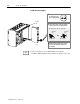
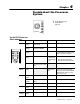
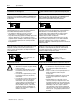
Install the PLC5 Processor
Define
the DH+ Station Address of Channel 1A
by setting switch assembly SW
1 on the back of
the processor.
Install the processor
.
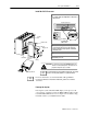
T
o install the battery, slide the batteryside
connector into the processor
side connector
until you hear them snap together
, and attach
the battery cover
.
side view
Set Switch
assembly SW1
address here
OFF
Battery
Connector
Battery Cover
Battery
1
2
4
More
For detailed information about handling and disposing of the battery
as well as other important guidelines, see publication AG5.4.
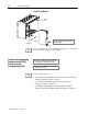
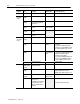
If
you plan to install an EEPROM, install it now
.
3
Memory
module slot
ATTENTION: Do not insert or remove the EEPROM under power
.
Insertion or removal under power can result in loss of
program memory and a processor fault.
Top
view of processor
Locking
Bar
PLC-5/25
Processor
Card Guides
Lift Eector T
ab
For more information, see the Classic PLC-5 Programmable
Controllers Hardware Installation Manual, publication number
1785-6.6.1.
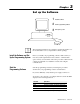
Powerup the System
Powerup the system. Check the LED display on the processor. If
your system is operating properly, the PROC LED should be steady
red. If the PROC LED is not red, see chapter 4 for troubleshooting
information before you install the I/O modules.
More