
QUICK START CLASSIC PLC-5 PROG Instruction Manual

2–3Set up the Hardware
Publication
178510.3 - October 1996
YN
20609-M
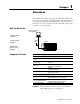
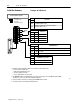
Keying
Bands
Set
the power supply configuration
jumper.
Install the keying bands.
Are
you using a power
supply module in
the chassis?
between
•40 & 42
•54 & 56
PLC5/20
Processor
I/O
Module
I/O
Module
2
3
NY
NY
Set
Y when you install a power
supply module in the chassis; set
N (the default) when you use an
external power supply
.
See the user manual
for your particular I/O
module for information
on where to set these
keying bands.
For more information, see the Universal I/O Chassis Installation
Instructions, publication number 1771-2.10.
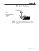
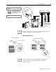
Ground the I/O Chassis
Enclosure
Grounding
electrode conductor
T
o grounding electrode system
Ground
bus
I/O chassis wall
Ground
lug
Nut
Star
washer
Ground lug
15561
(for remote I/O systems)
(for extendedlocal systems)
Extendedlocal I/O cables
Ground
bus
To
grounding
electrode
system
(single
point only)
I/O chassis
wall
Ground
lug
Nut
Star
washer
Ground lug
18585
Ground
bus
Enclosure
Enclosure
For more information, see the Allen-Bradley Programmable
Controller Wiring and Grounding Guidelines, publication
number 1770-4.1.
More
More