Allen Bradley Classic PLC 5 Programmable Controller (Cat. No.
Important User Information Because of the variety of uses for the products described in this publication, those responsible for the application and use of this control equipment must satisfy themselves that all necessary steps have been taken to assure that each application and use meets all performance and safety requirements, including any applicable laws, regulations, codes and standards.
Table of Contents Important User Information . . . . . . . . . . . . . . . . . . . . . . . . -1 Preface . . . . . . . . . . . . . . . . . . . . . . . . . . . . . . . . . . . . . . . P-1 Who Should Use This Manual . . . . . . . . . . . . . . . . . . . . . . . . . . . Purpose of This Manual . . . . . . . . . . . . . . . . . . . . . . . . . . . . . . . Related Documentation . . . . . . . . . . . . . . . . . . . . . . . . . . . . . Common Techniques Used in This Manual . . . . . . . . . . . . . . . . . .
Preface Preface Read this preface to familiarize yourself with the rest of the manual. This preface covers the following topics: • who should use this manual • the purpose of this manual • how to use this manual • conventions used in this manual • Allen-Bradley support Who Should Use This Manual Purpose of This Manual To use this manual, you should understand programmable controllers and be able to interpret the ladder logic instructions required to control your application.
P–2 Preface Related Documentation The following documents contain additional information concerning the products discussed in this manual. For more information about: See this document: Publication number: Classic PLC 5 programmable controllers Classic PLC 5 Programmable Controllers User Manual 1785 6.2.1 To obtain a free copy of this manual, complete and send in the User Manual Request Card that came packaged with this quick start. .
Preface Common Techniques Used in This Manual More Allen Bradley Support P–3 We use the following conventions throughout this manual: • Bulleted lists provide information, not procedural steps. • Numbered lists provide sequential steps or hierarchical information. We use this symbol to indicate additional references you can use when you need more information about a particular topic.
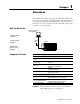
Chapter 1 Overview This quick start is designed to provide you with the information you need to get your system up and running quickly. Use this document if you are knowledgeable about Classic PLC-5 products, but may not have used one or more of them recently. The information we provide is geared to “jog your memory.
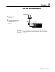
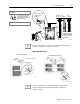
Chapter 2 Set up the Hardware 1 2 PC with programming software installed Install the hardware (page 2-2) Connect the programming terminal and the PLC 5 processor to the communication card (page 2 6) More terminal cable PLC 5/25 For more information, see the Classic PLC-5 Programmable Controllers Hardware Installation Manual, publication number 1785-6.6.1. Publication 1785 10.
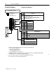
2–2 Set up the Hardware Install the Hardware 1 Configure the I/O Chassis Set the backplane switches. Switch Pressed in at top ON (closed) Last State 1 Pressed in at bottom OFF (open) Always Off ON Outputs of this I/O chassis remain in their last state when a hardware failure occurs. 1 OFF Outputs of this I/O chassis are turned off when a hardware failure occurs.
Set up the Hardware 2 Set the power supply configuration jumper. YN 3 YN Are you using a power supply module in the chassis? Set Y when you install a power supply module in the chassis; set N (the default) when you use an external power supply. PLC 5/20 Processor 2–3 I/O Module I/O Module Y N Install the keying bands. Keying Bands See the user manual for your particular I/O module for information on where to set these between keying bands.
2–4 Set up the Hardware Install the Power Supply 1 Set the jumpers on the back side of the power supply like this: Locking Bar 2 Connect the power cord to the 120V ac connector of the power supply module. This side plugs into connector on the module. insert wire here insert wire here or place tool here place tool here 3 Install the power supply in the chassis 20619-M More Publication 1785 10.3 - October 1996 and snap the module locking bar over the modules.
Set up the Hardware 2–5 Install the PLC 5 Processor 1 Define the DH+ Station Address of Channel 1A by setting switch assembly SW 1 on the back of the processor. Top view of processor side view Locking Bar OFF Lift Eector Tab Battery Connector Battery Cover Set Switch assembly SW1 address here 2 To install the battery, slide the battery side connector into the processor side connector until you hear them snap together, and attach the battery cover.
2–6 Set up the Hardware Install the I/O Modules Locking Bar Install each I/O module and connect the wiring arm. Card Guides 20618-M More Connect the Programming Terminal and the PLC 5 Processor to the Communication Card More For more information, see the installation instructions or user manual for the particular module you are installing. 1 Connect the industrial terminal end of the CP cable to the communication card. 2 Connect the CP cable to the connector on the PLC 5 processor.
Chapter 3 Set up the Software More Install the Software and Set Up the Programming System Start the Programming Software 1 Install the software 2 Start the programming software 3 Powerup the system The following instructions are general. For specific information, see the documentation set for your particular software package. Before you install your programming software, make certain you meet the system requirements for that software – sufficient disk space, memory, etcetera.
3–2 Set up the Software Powerup the System Powerup the system if you have not done so already. Check the LED display on the processor. If your system is operating properly, the PROC LED should be steady red. See the following table to proceed. If the PROC LED is not red, turn to chapter 4 for troubleshooting information. If your keyswitch is in this position: you see this message: and then this occurs: PROGRAM Processor RAM is faulted. Press to clear memory.
Chapter 4 Troubleshoot the Processor System BATT 1 PROC Use the PLC 5 Processor Status Indicators (page 4-1) FORCE COMM Use the PLC 5 Processor Status Indicators COMM FAULT Indicator Color Description Probable Cause Recommended Action PROC green (steady) processor in RUN mode and fully operational normal operation no action required green (blinking) Processor memory being transferred to EEPROM normal operation no action required red (blinking) major fault run time error Check majo
4–2 Troubleshoot the Processor System Indicator Color Description Probable Cause Recommended Action ADPT off processor is in scanner mode normal operation no action required REM I/O (in adapter mode) green (steady) active remote I/O link normal operation no action required green (blinking) remote I/O active and host processor is in program load or TEST mode normal operation no action required red (steady) no communication with host processor duplicate station address selected Correct
Appendix Specifications General This table lists general specifications. Weight Backplane Current PLC 5/10 (1785 LT4) 1336 g (47.12 oz.) PLC 5/12 (1785 LT3) 1337 g (42.15 oz.) PLC 5/15 (1785 LT) 1339 g (47.23 oz.) PLC 5/25 (1785 LT2) 1337 g (42.15 oz.) 2.
A–2 Specifications CSA Hazardous Location Approval Approbation d'utilisation dans des emplacements dangereux par la CSA CSA certifies products for general use as well as for use in hazardous locations. Actual CSA certification is indicated by the product label as shown below, and not by statements in any user documentation. La CSA certifie les produits d'utilisation générale aussi bien que ceux qui s'utilisent dans des emplacements dangereux.
Specifications A–3 This table lists specifications of each Classic PLC-5 family processor.
A–4 Specifications Battery Specifications Battery Type Classic PLC-5 processors use 1770-XY batteries, which contain less than 1/2 gram of lithium, or 3.6V, “AA” size Tadiran TL 5104 type AEL/S lithium batteries with pressure contact terminals. Average Battery Lifetime Specifications Publication 1785 10.3 - October 1996 At this temperature: Power off 100%: Power off 50%: 60°C 329 days 1.
Index Symbols **Empty**, -1, 3-1 B Backplane current, A-1 Battery, A-3 lifetime specifications, A-4 C Certification, A-1 Clock, processor, A-1 E I/O scan, discrete, A-1 P Processor, specifications, A-1 Processor memory, A-3 R Rack addressing capability, A-3 S Shock specifications, A-1 Specification, battery, A-4 Specifications, A-1 EEPROM, A-3 Environment specifications, A-1 I I/O addressing, A-1 V Vibration specifications, A-1
Allen Bradley Publication Problem Report If you find a problem with our documentation, please complete and return this form. Pub. Name Classic PLC 5 Programmable Controller Quick Start for the Experienced User Cat. No. 1785 LT, LT2, LT3, LT4 Pub. No. 1785 10.3 Check Problem(s) Type: Pub. Date October 1996 Part No.
PLEASE FASTEN HERE (DO NOT STAPLE) PLEASE FOLD HERE NO POSTAGE NECESSARY IF MAILED IN THE UNITED STATES BUSINESS REPLY MAIL FIRST-CLASS MAIL PERMIT NO.
Allen Bradley, a Rockwell Automation Business, has been helping its customers improve productivity and quality for more than 90 years. We design, manufacture and support a broad range of automation products worldwide. They include logic processors, power and motion control devices, operator interfaces, sensors and a variety of software. Rockwell is one of the world's leading technology companies. Worldwide representation.