
QUICK START CONTROLNET PLC-5


Chapter 1
Publication
1785-10.7 – October 1997
Before You Begin
The ControlNet network is a high-speed link that lets PLC
processors and I/O devices (e.g., I/O racks, variable speed drives,
Human-Machine Interface (HMI), and other automation devices)
exchange data. The ControlNet PLC-5 processors have one logical
ControlNet port consisting of two BNC connectors and one network
access port; these processors let you connect to the ControlNet
network.
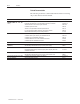
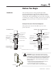
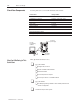
Identify the Processor’s Front Panel Components
These pictures show the ControlNet PLC-5 processor front
panel components.
Battery
Status Indicator
Processor RUN/F
AULT
Status Indicator
Force Status Indicator
Channel 0 Communication
ACTIVE/FAUL
T Status Indicator
Memory Module Space
Battery Compartment
Keyswitch
Channel 0
DH+ Programming T
erminal
Connection to Channel 1A
Channel 2 ControlNet
Status Indicators
Channel 2
➀
ControlNet
I/O Status Indicator
ControlNet Network Access
Port
Channel 1 Status Indicators
Channel 1A
Channel 1B
Memory Module Space
Battery Compartment
Channel 0
Keyswitch
ControlNet I/O Status Indicator
Channel 2 ControlNet
Status Indicators
ControlNet Network Access Port
Channel 2
➀
Channel 1 Status Indicators
DH+ Programming T
erminal
Connection to Channel 1A
Channel 1A
Channel 1B
Battery Status Indicator
Processor RUN/F
AULT
Status Indicator
Force Status Indicator
Channel 0 Communication
ACTIVE/FAUL
T Status
Indicator
PLC-5/20C Processor
PLC-5/40C, -5/60C, and -5/80C Processors
➀
ControlNet Redundant Media Ports— BNC; dedicated
ATTENTION: Make sure you understand the anti-static environment.
The processor is shipped in a static-shielded container to guard against
electrostatic damage. Electrostatic discharge can damage integrated circuits
or semiconductors in the processor module if you touch backplane connector
pins. It can also damage the module when you set configuration plugs or
switches inside the module. Avoid electrostatic damage by observing the
following precautions.
• Remain in contact with an approved ground point while handling the
module (by wearing a properly grounded wrist strap).
• Do not touch the backplane connector or connector pins.
• When not in use, keep the module in its static-shielded container.
Wrist strap
Introduction