
QUICK START CONTROLNET PLC-5

2–5Set Up the Hardware
Publication
1785-10.7 – October 1997
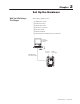
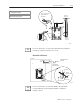
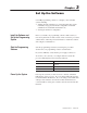
Install the PLC-5 Processor
Card Guides
Lift Ejector Tab
20610–M
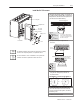
Define
the DH+ Station Address of Channel 1A
by setting switch assembly SW
-1 on the back of
the processor
. (See the side of the processor if
you want to use another address.)
side
view of processor
side view
1234567
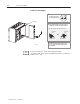
Battery Connector
Battery Cover
Battery
1
4
5
PLC-5/20
Processor
Locking Bar
2
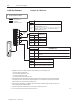
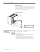
Specify
the serial port configuration for
channel 0.
Front
of
Processor
1
2345 678910
1
2345 678 910
Front of
Processor
bottom
view of PLC-5/20C processor
bottom view of PLC-5/40C and -5/80C processor
side view
OFF
More
For more information, see the ControlNet PLC-5 Programmable
Controllers User Manual, publication number 1785-6.5.14.
More
For detailed information about handling and disposing of the battery
as well as other important guidelines, see publication AG-5.4.
up
230
Kbaud
down
57.6 Kbaud
For
series E and later processors:
use this switch to select baud rate
For series D and earlier processors:
this switch is always of
f
Install
the processor module.
T
o install the battery, slide the battery-side
connector into the processor
-side connector
until you hear them snap together
, and attach
the battery cover
.
3
Set the ControlNet network addresses by
using the two 10-digit rotary switches on
top of the module.
90
ControlNet PLC-5 processor’s NET address = 1
10
00
80 70
60
50
40
20 30
9
1
0
87
6
5
4
23