Allen-Bradley ControlNet PLC-5 Programmable Controllers Cat. No. 1785-L20C, -L40C, -L60C, -L80C product icon Quick Start Phase 1.
Important User Information Because of the variety of uses for the products described in this publication, those responsible for the application and use of this control equipment must satisfy themselves that all necessary steps have been taken to assure that each application and use meets all performance and safety requirements, including any applicable laws, regulations, codes and standards.
Preface Preface Read this preface to familiarize yourself with the rest of the manual. This preface covers the following topics: • who should use this manual • the purpose of this manual • conventions used in this manual • Rockwell Automation support Who Should Use this Manual Use this manual if you are new to the ControlNet PLC-5 processor. Purpose of this Manual This manual introduces you to installing and using a ControlNet PLC-5 processor system.
P–2 Preface Related Documentation The following documents contain additional information concerning the products discussed in this manual. For more information about: See this publication: Publication number: ControlNet ontrol et P PLC-5 -5 programmable ro ra able controller (1785-L20C, controllers 1785- 0 -L40C, - 0 and an - 80 ) -L80C) ControlNet PLC-5 Programmable Controllers User Manual, phase 1.
Preface Conventions Used in This Manual " P–3 The following conventions are used throughout this manual: • Bulleted lists provide information, not procedural steps. • Numbered lists provide sequential steps or hierarchical information. • Italic type is used for emphasis. • Text in this font indicates words or phrases you should type. • Key names match the names shown and appear in bold, capital letters (for example, ENTER). Tip: We use this convention to call attention to helpful information.
P–4 Preface Rockwell Automation Support Rockwell Automation offers support services worldwide, with over 75 Sales/Support Offices, 512 authorized Distributors and 260 authorized Systems Integrators located throughout the United States alone, plus Allen–Bradley representatives in every major country in the world.
Table of Contents Before You Begin Chapter 1 Introduction . . . . . . . . . . . . . . . . . . . . . . . . . . . . . . . . . . . . . . . . . Identify the Processor’s Front Panel Components . . . . . . . . . . . . . . Check Your Components . . . . . . . . . . . . . . . . . . . . . . . . . . . . . . . Set Up the Hardware Chapter 2 What You’ll Be Doing in This Chapter . . . . . . . . . . . . . . . . . . . . . . Configure the I/O Chassis . . . . . . . . . . . . . . . . . . . . . . . . . . . . . . .
toc–ii Table of Contents Notes: Publication 1785-10.
Chapter 1 Before You Begin Introduction The ControlNet network is a high-speed link that lets PLC processors and I/O devices (e.g., I/O racks, variable speed drives, Human-Machine Interface (HMI), and other automation devices) exchange data. The ControlNet PLC-5 processors have one logical ControlNet port consisting of two BNC connectors and one network access port; these processors let you connect to the ControlNet network.
1–2 Before You Begin Check Your Components For this quick start, you need this hardware and software: Product name: Catalog number: Hardware ControlNet PLC-5 processor ControlNet network access cable 1771 I/O chassis power supply personal computer communication interface card 1785-L20C, -L40C, L60C, -L80C 1786-CP 1771-A1B 1771-P4S your choice 1784-KTCx Software RSLogix5 programming software 6200 programming software RSLinx communication software 1771-P4S power supply PC with Programming Software 1
Before You Begin Compliance to European Union Directives 1–3 If this product has the CE mark it is approved for installation within the European Union and EEA regions. It has been designed and tested to meet the following directives.
1–4 Before You Begin Notes Publication 1785-10.
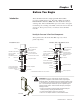
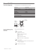
Chapter 2 Set Up the Hardware What You’ll Be Doing in This Chapter This chapter explains how to: - Configure the I/O chassis - Ground the I/O chassis - Install the power supply - Install the PLC-5 processor - Power up the system - Install the I/O modules - Connect the personal computer to the PLC-5 processor PC with Programming Software PLC-5/20C Processor Internal Power Supply ControlNet network access cable (1786-CP) Publication 1785-10.
2–2 Set Up the Hardware Install the Hardware 1 Configure the I/O Chassis Set the backplane switches. Pressed in at top ON (closed) Switch Pressed in at bottom OFF (open) Last State 1 on Outputs of this I/O chassis remain in their last state when a hardware failure occurs. ➀ off Outputs of this I/O chassis are turned off when a hardware failure occurs.
Set Up the Hardware 2–3 2 Set the power supply configuration jumper. Are you using a power supply module in the chassis? 3 Install the keying bands. PLC-5/20 Processor Y N Keying Bands between • 40 & 42 • 54 & 56 20609–M More For more information, see the Universal I/O Chassis installation instructions, publication number 1771-2.10.
2–4 Set Up the Hardware Install the Power Supply 1 Set the jumpers on the back side of the power supply like this: locking bar 2 Connect the power cord to the 120V ac connector of the power supply module. This side plugs into connector on the module. insert wire here insert wire here or place tool here place tool here 3 Install the power supply in the chassis 20619–M More Publication 1785-10.7 – October 1997 and snap the module-locking bar over the modules.
Set Up the Hardware 2–5 Install the PLC-5 Processor 1 Define the DH+ Station Address of Channel 1A by setting switch assembly SW-1 on the back of the processor. (See the side of the processor if you want to use another address.) Locking Bar side view of processor Lift Ejector Tab PLC-5/20 Processor 1 2 3 4 5 6 7 Battery Connector side view Battery Cover For series E and later processors: use this switch to select baud rate For series D and earlier processors: this switch is always off down 57.
2–6 Set Up the Hardware Powerup the System Powerup the system. Check the LED display on the processor. If your system is operating properly, the PROC LED should be steady red. If the PROC LED is not red, see chapter 4 for troubleshooting information before you install any I/O modules. Install the I/O Modules Locking Bar Install each I/O module and connect the wiring arm.
Chapter 3 Set Up the Software Use 6200 programming software to configure your ControlNet system, including: • defining network parameters (i.e. network update time, media redundancy usage, physical media configuration, maximum scheduled node, maximum unscheuled node) • entering the channel 2 configuration Install the Software and Set Up the Programming System Before you install your programming software, make certain you meet the requirements for that software.
3–2 Variable Content TTL:Chap Is Linked To HD:Running Notes: Publication 1785-10.
Chapter 4 Troubleshoot the Processor System Using This Chapter If you want to read about: Using the general status indicators Using the ControlNet status indicators Monitoring the ControlNet configuration and status screens Using the General Status Indicators See page: 4-1 4-3 4-6 The general status indicators inform you of the general operational state of the processor.
4–2 Troubleshoot the Processor System Indicator Color Description Probable Cause Recommended Action FORCE Amber (steady) SFC and/or I/O forces enabled Normal operation No action required Amber (blinking) SFC and/or I/O forces present but not enabled Off SFC and/or I/O forces not present Off No transmission on channel 0 Normal operation if channel is not being used Green (blinking) Transmission on channel 0 Normal operation if channel is being used COMM Publication 1785-10.
Troubleshoot the Processor System Using the ControlNet Status Indicators Indicator I/O I/O The ControlNet status indicators inform you of the operational state of the ControlNet network.
4–4 Troubleshoot the Processor System ColorÀ Off Indicator Probable Cause Internal diagnostics failed Recommended Action 1. Turn power off, make sure ControlNet address is not 00, reseat processor, then power up 2. Clear memory and reload your program 3. Replace EEPROM with new program 4. If still an error, replace the processor No power Check power supply Faulted unit Cycle power or reset unit and B A Steady Red If fault persists, contact your Allen-Bradley Company, Inc.
Troubleshoot the Processor System 4–5 Using the DH+/RIO Status Indicators Indicator Color A or B Channel Mode Description Probable Cause Recommended Action Remote I/O Scanner Active Remote I/O link, all adapter modules are present and not faulted Normal operation No action required Remote I/O Adapter Communicating with scanner DH+ Processor is transmitting or receiving on DH+ link Remote I/O Scanner At least one adapter is faulted or has failed • Power off at remote rack • Cable broken • R
4–6 Troubleshoot the Processor System Monitoring ControlNet Configuration and Status More Publication 1785-10.7 – October 1997 Use 6200 programming software to monitor ControlNet configuration and status information, including: • ControlNet configuration • map entry status • I/O action • network and node status For information about using 6200 programming software or RSLogix5 software, see the online help systems or contact your local Allen-Bradley representative.
Appendix A Processor Specifications Backplane Current (3 Amps @ 5V dc) Heat Dissipation Environmental Conditions Shock Vibration Time-of-Day C o /C n ¬ Clock/Calendar¬ Battery Memory Modules I/O Modules Hardware Addressing Communication Location Weight Keying Agency Certification (When product or packaging is marked) PLC-5/20C: 2.7A PLC-5/40C, -5/60C, -5/80C: 3.
A–2 Processor Specifications Maximum User Memory Words Maximum Any Mix Total o I/O Complimentary Program Scan Time ControlNet I/O® Transmission Rate Network Update Time (NUT) Number of ControlNet Ports Maximum Number of Nodes per Link without a Repeater Maximum Number of Nodes per Link with Repeaters Maximum Link Cable Length without a Repeater Maximum DIF/DOF Size Maximum Link Cable Length with Repeaters Remote I/O and DH+ Transmission Rate I/O Scan Time (Typical) PLC-5/20C PLC-5/40C PLC-5/60C 16K
Variable Content TTL:Chap A–3 CSA Hazardous Location Approval Approbation d’utilisation dans des emplacements dangereux par la CSA CSA certifies products for general use as well as for use in hazardous locations. Actual CSA certification is indicated by the product label as shown below, and not by statements in any user documentation. La CSA certifie les produits d’utilisation générale aussi bien que ceux qui s’utilisent dans des emplacements dangereux.
A–4 Processor Specifications Notes Publication 1785-10.
Allen-Bradley Publication Problem Report If you find a problem with our documentation, please complete and return this form. Pub. Name ControlNet PLC-5 Programmable Controllers Quick Start, Phase 1.25 Cat. No. 1785-L20C, -40C, -60C, -80C Check Problem(s) Type: Pub. No. 1785-10.7 Pub. Date October 1997 Part No.
PLEASE FASTEN HERE (DO NOT STAPLE) PLEASE FOLD HERE NO POSTAGE NECESSARY IF MAILED IN THE UNITED STATES BUSINESS REPLY MAIL FIRST-CLASS MAIL PERMIT NO.
Allen-Bradley, a Rockwell Automation Business, has been helping its customers improve productivity and quality for more than 90 years. We design, manufacture and support a broad range of automation products worldwide. They include logic processors, power and motion control devices, operator interfaces, sensors and a variety of software. Rockwell is one of the world’s leading technology companies. Worldwide representation.