
User Manual Owner manual


Chapter 5
Monitoring and Troubleshooting Your
ControlNet System
5-6
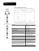
Using the ControlNet Node Information (Monitor) Screen
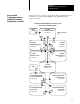
Follow the steps on the left to go to the ControlNet Node Information
(Monitor) screen.
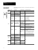
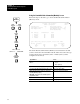
ControlNet - Node Information MONITOR
Channel 2 Configuration NODE 1
Diagnostics File: N12 Network Update Time(ms): 5
Coax Repeaters in Series: 1 Scheduled Bandwidth Usage: 64%
Fiber Repeater Pairs: 0 Media Redundancy Usage: A Only
Maximum Scheduled Node: 10
Node Node Type Series/Revision Status
1 PLC-5/40C C/H ACTIVE
2 1771-ACN A/A ACTIVE
3 PLC-5/20C C/H ACTIVE
4 1794-ACN A/A ACTIVE
Press a function key, page up or page down, or enter a node. number.
>
Rem Prog Forces:None 5/40C File CN
Map Node Define Chan 2
Monitor Edit LclRack Status
F2 F4 F7 F9
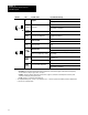
The ControlNet Node Information (Monitor) screen lists the nodes that
you have entered for the ControlNet network; and it shows the node type,
product series/revision, and status (active or inactive) that you have
configured for each node.
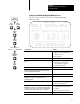
If you want to: Press:
quickly position the cursor on a specific node in
the list
1. Type the node number and a period (.)
e.g., 2.
2. Press [Enter]
go to the ControlNet I/O Mapping (Monitor) screen
Press [F2]—Map
Monitor
go to the ControlNet Node Information (Edit) screen
Press [F4]—Node
Edit
define the characteristics of the local chassis (for
reserving I/O image space)
Important: This option is not available if you are
programming online.
Press [F7]—Define
LclRack
go to the ControlNet Channel 2 Status screen Press [F9]—Chan
2
Status
go to the Channel Overview screen Press [Esc]
Channel
Overview
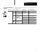
6200
Main Menu
General
Utility
F7
F4
Channel
Configuration
F5
(Monitor)
Move cursor to
Channel 2: CONTROLNET
F3
Online
Program
Offline
Program
F1
or