
User Manual Owner manual


Chapter 4
Programming Your ControlNet System
4-5
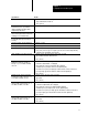
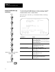
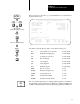
Follow the steps on the left to go to the Data Monitor for ControlNet I/O
Transfer Block screen.
Data Monitor for ControlNet I/O Transfer Block CT21:50
Communication Command: 1771 Write
PLC-5 Data Table Address: N7:3 ignore if timed-out: 0 TO
Size in Elements: 10 awaiting execution: 0 EW
Elements Transmitted: 0 continuous: 0 CO
error: 0 ER
transfer done: 0 DN
Local ControlNet Node: 1 transfer started: 0 ST
Slot Number: 0 transfer enabled: 0 EN
Port Number: 2
Error Code: 0000 (HEX)
Press a function key or enter a value.
CT21:50.TO =
Rem Prog Forces:None Data:Decimal Addr:Decimal 5/40C File CN
Toggle Size in Specify Next Prev Next Prev
Bit Elemnts Address File File Element Element
F2 F3 F5 F7 F8 F9 F10
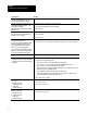
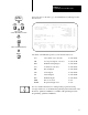
The fields of the CT data type that you can directly address are:
.TO Abort (Time out) control bit word 0, bit 08
.EW Enabled-waiting flag bit word 0, bit 02
.CO Continuous control bit word 0, bit 03
.ER Errored flag bit word 0, bit 04
.DN Done flag bit word 0, bit 05
.ST Started flag bit word 0, bit 06
.EN Enabled flag bit word 0, bit 07
.ERR Error-code word word 1
.RLEN Requested length word word 2
.DLEN Done length word word 3
.FILE Transfer file number word 4
.ELEM Transfer element number word 5
For more detailed information on writing ladder programs, see the PLC-5
Programming Software Instruction Set Reference, publication 6200-6.4.11,
and PLC-5 Programming Software Programming, publication 6200-6.4.7.
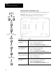
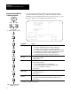
Monitor
File
6200
Main Menu
Cursor to file;
F3
Online
Program
Offline
Program
F1
or
F8
Data
Monitor
F8
or enter file number or name
Cursor to CIO instruction
Monitor
File
F3
More